Variable air volume adjusting valve applied to purification equipment

A technology of purification equipment and regulating valves, applied in the field of regulating valves, can solve the problems of shortening the service life of regulating valves, easy to freeze, freezing of regulating valves, etc., and achieve the effects of prolonging service life, improving stability and reducing failure rate

Inactive Publication Date: 2021-08-03
深圳市贵庭机电设备有限公司
View PDF4 Cites 0 Cited by
  • Summary
  • Abstract
  • Description
  • Claims
  • Application Information

AI Technical Summary

Problems solved by technology

[0003] The air volume regulating valve is a common part in the purification equipment, which can ensure the normal operation of the purification equipment. However, the existing regulating valve is not equipped with a protective mechanism to protect it. The regulating valve is easy to shake under the action of internal pressure during use, and long-term use will cause The control valve is damaged, which shortens the service life of the control valve. Today's air volume control valve has a simple structure and can only perform simple adjustments. When there are impurities in the wind, the impurities and them are easy to accumulate inside the valve core, causing the valve to not operate normally. And in cold weather, the moisture in the air is easy to freeze, so that the regulating valve freezes, causing the regulating valve to fail to work.

Method used


Image

  • Variable air volume adjusting valve applied to purification equipment
  • Variable air volume adjusting valve applied to purification equipment
  • Variable air volume adjusting valve applied to purification equipment

Examples


Embodiment 1

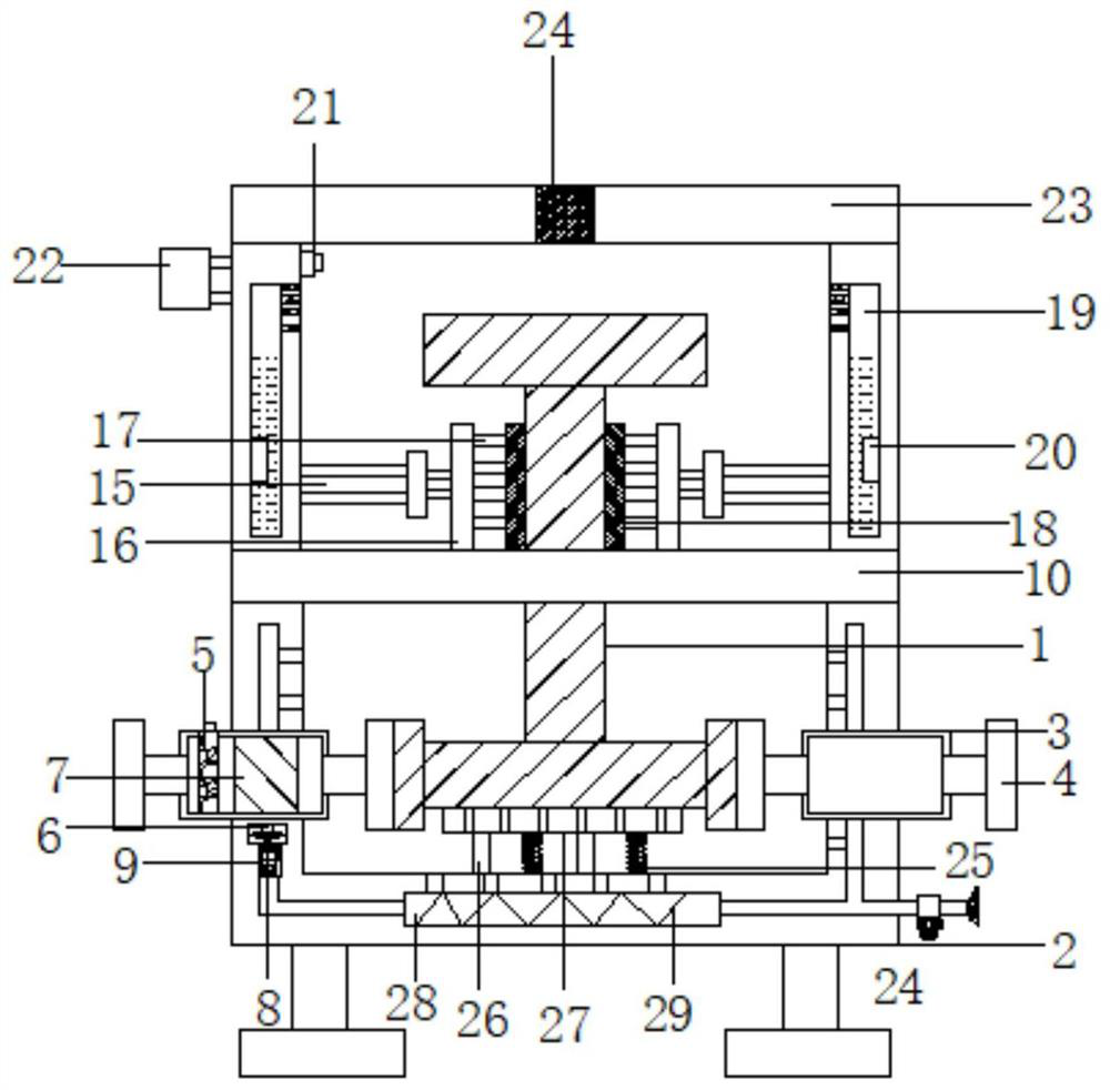
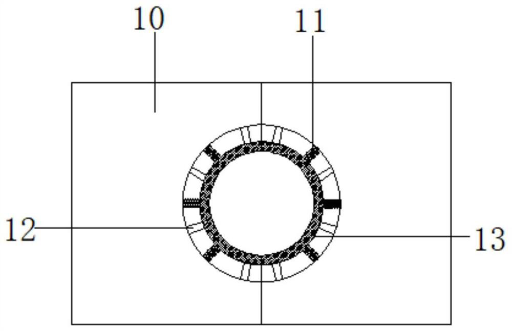
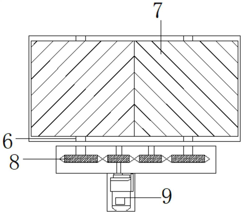
[0023] Embodiment 1, with reference to Figure 1-4 , a variable air volume regulating valve applied to purification equipment, including a regulating valve body 1 and a protective mechanism, the protective mechanism includes a base 2, and the outer walls on both sides of the base 2 are provided with connecting grooves 3, and the outer walls on both sides of the connecting groove 3 are A flange 4 is provided, and the inner wall of the connecting groove 3 on one side is slidingly connected with the adsorption cage 5, and the inner wall of the connecting groove 3 is rotatably connected with the connecting shaft 6, and the outer wall of the connecting shaft 6 is welded with a baffle plate 7, and the base 2 is close to the connecting There is a control groove on the outer wall of one side of the shaft 6, and the connecting shaft 6 is connected to the inside of the control groove, and the end of the connecting shaft 6 is welded with a drive plate 8, and the inner wall of the control ...


PUM


Abstract

The invention discloses variable air volume adjusting valve applied to purification equipment, comprising an adjusting valve body and a protection mechanism. The protection mechanism comprises a base; connecting grooves are formed in the outer walls of the two sides of the base; flanges are arranged on the outer walls of the two sides of the connecting grooves; the inner wall of the connecting groove on one side is slidably connected with an adsorption net cage; the inner wall of the connecting groove is rotatably connected with a connecting shaft; a baffle is welded to the outer wall of the connecting shaft; a control groove is formed in the outer wall of the side, close to the connecting shaft, of the base; the connecting shaft penetrates into the control groove; a driving disc is welded to the tail end of the connecting shaft; a gear disc is rotationally connected to the inner wall of the control groove and meshed with the control disc; and a driving groove is formed below the control groove. According to the adjusting valve, a damping spring, a damping sponge, a protective pad, a buffering cotton strip, a buffering spring and a buffering cotton swab act together, so that vibration generated when the adjusting valve body works is reduced, the stability of the adjusting valve is kept, the influence of continuous vibration of the adjusting valve body in the working process on the service life of the adjusting valve body is reduced, and the service life of the adjusting valve body is prolonged.

Description

technical field [0001] The invention relates to the technical field of regulating valves, in particular to a variable air volume regulating valve applied to purification equipment. Background technique [0002] Regulating valves play a very important role in the automatic control of modern factories whose production depends on the correct distribution and control of the flowing medium. Whether these controls are energy exchange, pressure reduction or simple container filling, some final control elements are required to complete. A regulating valve acts as a variable resistance in a pipeline. [0003] The air volume regulating valve is a common part in the purification equipment, which can ensure the normal operation of the purification equipment. However, the existing regulating valve is not equipped with a protective mechanism to protect it. The regulating valve is easy to shake under the action of internal pressure during use, and long-term use will cause The control val...

Claims


Application Information

Patent Timeline
Patent Type & Authority Applications(China)
IPC IPC(8): F16K27/00F16K1/22F16K1/32F16K27/02F16K31/04F16K31/53F16K27/12F16K37/00F16K49/00F16K51/00F16F15/08F16F15/02B01D46/10B01D46/00
CPCF16K27/00F16K1/223F16K1/32F16K27/0218F16K31/043F16K31/535F16K27/12F16K37/0075F16K49/00F16K51/00F16F15/085F16F15/02B01D46/10B01D46/0036
Inventor 何小东
Owner 深圳市贵庭机电设备有限公司
Why Eureka
Try Eureka