Water tank of heat pump water heater and hot water system

A technology for heat pump water heaters and water tanks, which is applied to fluid heaters, lighting and heating equipment, mechanical equipment, etc., can solve the problems of poor water experience and inability to pressurize the water flow of cold water pipes, and achieves simple structure, easy implementation, and convenient use. Effect

Pending Publication Date: 2021-08-03
QINGDAO HAIER NEW ENERGY ELECTRIC APPLIANCE +2
View PDF5 Cites 0 Cited by
  • Summary
  • Abstract
  • Description
  • Claims
  • Application Information

AI Technical Summary

Problems solved by technology

In the case of low water pressure in the waterway of the whole house, the purpose of pressurizing the water flow in the cold water pipe cannot be achieved, and the user's water experience is poor

Method used


Image

  • Water tank of heat pump water heater and hot water system
  • Water tank of heat pump water heater and hot water system
  • Water tank of heat pump water heater and hot water system

Examples


Embodiment 1

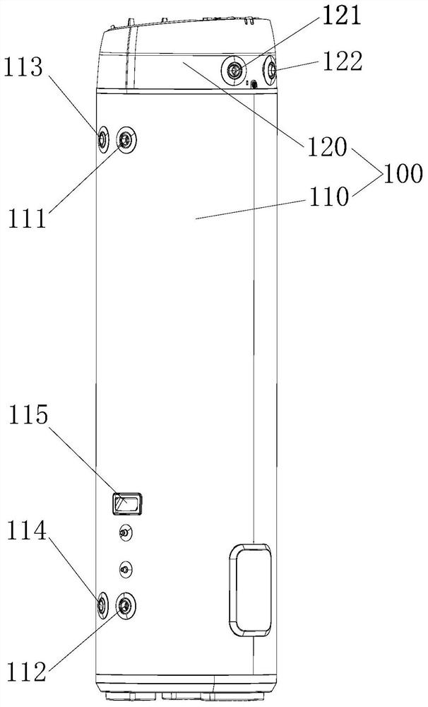
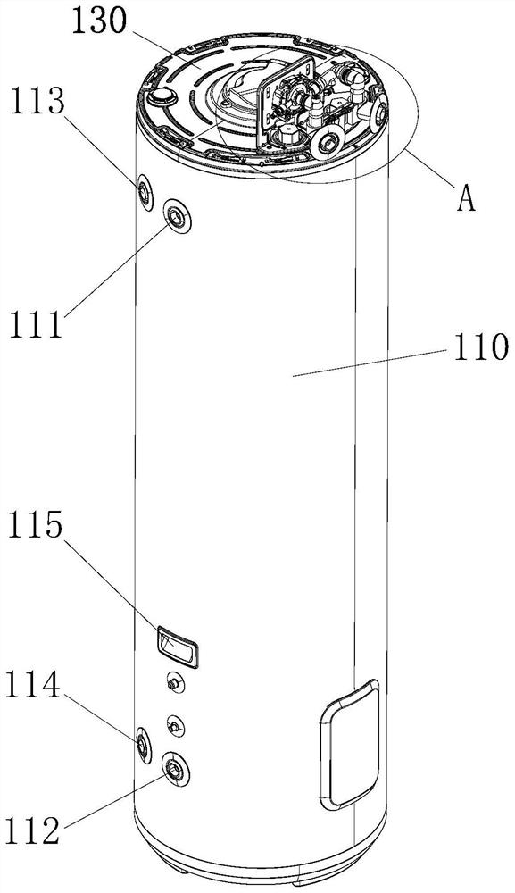
[0049] Such as Figure 1 to Figure 5 As shown, the water tank of the heat pump water heater in this embodiment includes an outer shell 100 and an inner tank arranged in the outer shell 100 . The water tank of the heat pump water heater is provided with a first water inlet 121 , a cold water outlet 122 and a hot water outlet 111 , and the hot water outlet 111 is arranged on the shell 100 and communicated with the inner tank.

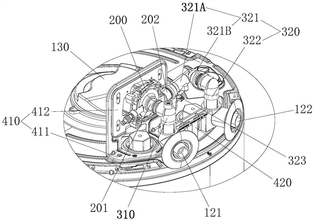
[0050] The water tank of the heat pump water heater also includes a booster pump 200 , the first water inlet 121 communicates with the water inlet 201 of the booster pump 200 , and the water outlet 202 of the booster pump 200 communicates with the cold water outlet 122 . The cold water outlet 122 communicates with the inner tank through a communication pipeline (not shown in the figure).

[0051] In this embodiment, the water tank of the heat pump water heater is equipped with a booster pump 200 , and the external water supply enters from the first water...

Embodiment 2

[0091] Such as Figure 6 As shown, the hot water system described in this embodiment includes the heat pump water heater water tank 1 described in the first embodiment above, and several water points 5 . The first water inlet 121 on the water tank 1 of the heat pump water heater is connected to an external water source, and the hot water outlet 111 is connected to each water point 5 through a hot water pipe 3 .

[0092] The hot water system also includes a cold water pipe 4 connected to each water point 5 , and the water inlet end of the cold water pipe 4 is connected to the communication pipeline 2 between the cold water outlet 122 and the second water inlet 112 .

[0093] In the above scheme, the water tank 1 of the heat pump water heater is directly installed at the water inlet of the whole house and connected with an external water source. Specifically, the water in the tap water well is pumped into the water storage tank in the user's home for storage, and when the user ...


PUM


Abstract

The invention belongs to the technical field of water heaters and discloses a water tank of a heat pump water heater and a hot water system. The water tank of the heat pump water heater comprises a shell and an inner container arranged in the shell, wherein the water tank of the heat pump water heater is provided with a first water inlet, a cold water outlet and a hot water outlet, and the hot water outlet is formed in the shell and communicated with the inner container; the water tank of the heat pump water heater further comprises a booster pump, the first water inlet is communicated with the water inlet end of the booster pump, and the water outlet end of the booster pump is communicated with the cold water outlet; and the cold water outlet is communicated with the inner container through a communicating pipeline. The water tank of the heat pump water heater is provided with the booster pump, water flow boosted by the booster pump flows out of the cold water outlet and can be directly supplied with cold water or enter the inner container through the communicating pipeline to be heated, and the purpose of boosting hot water and cold water in the water path at the same time can be achieved only by connecting an external water source to the first water inlet.

Description

technical field [0001] The invention belongs to the technical field of water heaters, and in particular relates to a heat pump water heater water tank and a hot water system. Background technique [0002] The working principle of the heat pump water heater is that the low-temperature and low-pressure refrigerant liquid in the evaporator absorbs the heat in the air to vaporize the refrigerant into a low-temperature and low-pressure refrigerant gas, and then compresses and presses the refrigerant through the compressor to become a high-temperature and high-pressure gas. The heat exchanger in the water tank exchanges heat with the water in the water tank to heat up the water in the water tank. At the same time, the refrigerant turns into a low-temperature and high-pressure liquid through the heat exchange process, and then becomes a low-temperature and low-pressure liquid through the throttling device, and then enters the evaporator again to repeat the above process. Tradition...

Claims


Application Information

Patent Timeline
Patent Type & Authority Applications(China)
IPC IPC(8): F24H9/00F24H9/12F24H9/20F24H4/02
CPCF24H9/0005F24H9/2007F24H4/02F24H9/13
Inventor 赵润鹏黄娟杜顺祥余锦剑陈炳泉徐洪昊杨伟孟得林张益民郑记莘李羲龙
Owner QINGDAO HAIER NEW ENERGY ELECTRIC APPLIANCE
Why Eureka
Try Eureka