
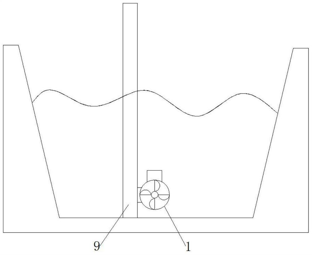
River water flow velocity monitoring equipment

A technology for monitoring equipment and water flow velocity, which is applied in fluid velocity measurement, mechanical equipment, velocity/acceleration/shock measurement, etc. It can solve the problems of alarm transmission to monitoring personnel, increasing the budget of river water flow monitoring, and being easily destroyed by water flow, etc.

Pending Publication Date: 2021-08-03
鲜永敏
View PDF11 Cites 0 Cited by
  • Summary
  • Abstract
  • Description
  • Claims
  • Application Information

AI Technical Summary

Problems solved by technology

[0005] The purpose of the present invention is to provide a river water flow rate monitoring device to solve the problem that the above-mentioned traditional river water flow rate monitoring device cannot timely communicate the alarm to the monitoring personnel when monitoring the river, thereby causing irreparable losses; It is easy to be washed away by water flow, which increases the budget for river flow monitoring

Method used


Image

  • River water flow velocity monitoring equipment
  • River water flow velocity monitoring equipment
  • River water flow velocity monitoring equipment

Examples


Embodiment 1

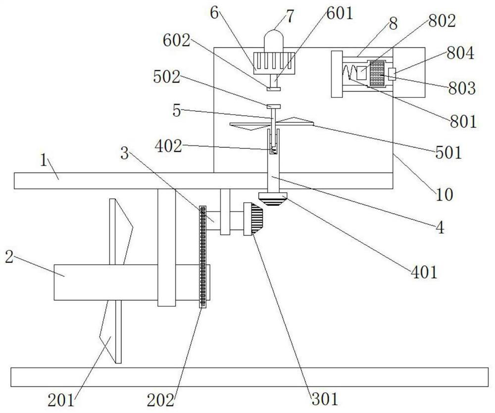
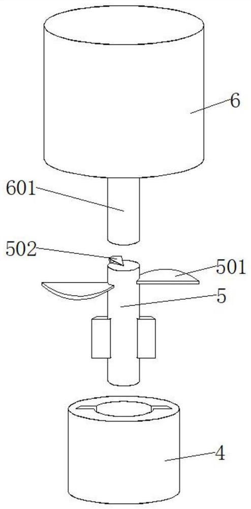
[0028] The present invention provides a river water flow rate monitoring device. The river water flow rate monitoring device includes a water flow rate monitoring shell 1; mechanism.

[0029] Wherein, the fluid follow-up mechanism includes: rotating shaft A2, fan blade A201, chain 202, rotating shaft B3, bevel gear A301;

[0030] One side of the water flow rate monitoring housing 1 is rotatably installed with a rotating shaft A2, and one side of the rotating shaft A2 is fixedly equipped with fan blades A201, and the number of fan blades A201 is several, and the other side of the rotating shaft A2 is movably connected with a rotating shaft B3 through a chain 202, and the rotating shaft B3 is rotatably connected to the bottom of the water flow rate monitoring housing 1, and a bevel gear A301 is fixedly installed on one side of the rotating shaft B3. Rotating the chain 202 drives the rotating shaft B3 to rotate.

[0031] Among them, the heat trigger mechanism includes: rotating...

Embodiment 2

[0036] The present invention also includes an automatic protection mechanism, which includes an airbag trigger clamping case 8, a spring B801, an elastic block 802, a temperature-sensitive glass ball 803, and an airbag 804;

[0037] Wherein, the inner side above the sealed cavity 10 is fixedly equipped with an airbag triggering clamping case 8, and the outside of the airbag triggering clamping housing 8 is wound with several coils of heating wires, and the heating wire is connected with the generator 6, and the inner bottom side of the airbag triggering clamping housing 8 is fixedly installed with a spring. B801, spring block 802 is fixedly installed on the other side of spring B801, and temperature-sensitive glass ball 803 is provided inside the airbag trigger jam shell 8, and the temperature-sensitive glass ball 803 is F1.5 extremely fast response type, and the airbag trigger jam shell 8 is inside another One side is equipped with an airbag 804, and the positions of the elast...


PUM


Abstract

The invention provides river water flow velocity monitoring equipment. The river water flow velocity monitoring equipment comprises a water flow velocity monitoring shell, wherein a rotating shaft is rotatably installed on one side in the water flow velocity monitoring shell, fan blades are fixedly installed on one side of the rotating shaft, a chain is movably connected to the other side of the rotating shaft, a rotating shaft B is rotatably connected to one side of the bottom of the water flow velocity monitoring shell, and a bevel gear is fixedly installed on one side of the rotating shaft B. The rotating shaft and the fan blades are arranged according to the flow velocity of river water, the fan blades drive the rotating shaft to rotate, the rotating shaft rotates the chain to drive a rotating shaft B to rotate, then impact force brought by the flow velocity of the river water is converted into rotating force needed by equipment, the bevel gear drives a bevel gear B to rotate so as to drive a rotating shaft C to rotate, and the rotating velocity of the subsequent rotating shaft is accelerated, and the rotating force brought by the flow velocity of river water is amplified.

Description

technical field [0001] The invention relates to the technical field of river monitoring, in particular to a river water velocity monitoring device. Background technique [0002] Rivers refer to precipitation or water gushing out of the ground that gathers in low-lying places on the ground, and often or periodically flows along the depressions caused by the flowing water itself under the action of gravity. Where the slope is large, the river speed is fast, and the land will be severely eroded , so that the water and soil loss on both sides of the bank will be too fast and cause bad effects. For this, we need to make an early warning when the river flows too fast. [0003] The traditional river water flow rate monitoring equipment cannot timely convey the alarm to the monitoring personnel when monitoring the river, so that the monitoring personnel cannot make preparations for the sudden excessive water flow rate, causing the land on the river bank to be impacted and collapsed ...

Claims


Application Information

Patent Timeline
Patent Type & Authority Applications(China)
IPC IPC(8): G01P1/00G01P1/07G01P5/07F03B17/06
CPCG01P1/00G01P1/07G01P5/07F03B17/06F05B2260/4022F05B2260/4031Y02E10/20
Inventor 鲜永敏
Owner 鲜永敏
Learn More