Optical cable fault detection device and detection method thereof

A fault detection and optical cable technology, applied in electromagnetic wave transmission systems, electrical components, transmission systems, etc., can solve the problems of inability to detect the loss of optical fiber joints and optical fiber joints, and achieve reasonable structure, offset loss, and convenient use. Effect

Active Publication Date: 2021-08-03
ELECTRIC POWER SCI RES INST OF STATE GRID XINJIANG ELECTRIC POWER +2
View PDF7 Cites 0 Cited by
  • Summary
  • Abstract
  • Description
  • Claims
  • Application Information

AI Technical Summary

Problems solved by technology

[0004] The present invention provides an optical cable fault detection device and a detection method thereof, which overcomes the deficiencies of the prior art above, and can effectively solve the problem that existing optical time domain reflectometers cannot detect optical fiber joints during the detection of optical fiber joints. The loss of the connector is detected, so that the loss of the fiber connector leads to errors in the detection of the fiber connector

Method used


Image

  • Optical cable fault detection device and detection method thereof
  • Optical cable fault detection device and detection method thereof
  • Optical cable fault detection device and detection method thereof

Examples


Embodiment 1

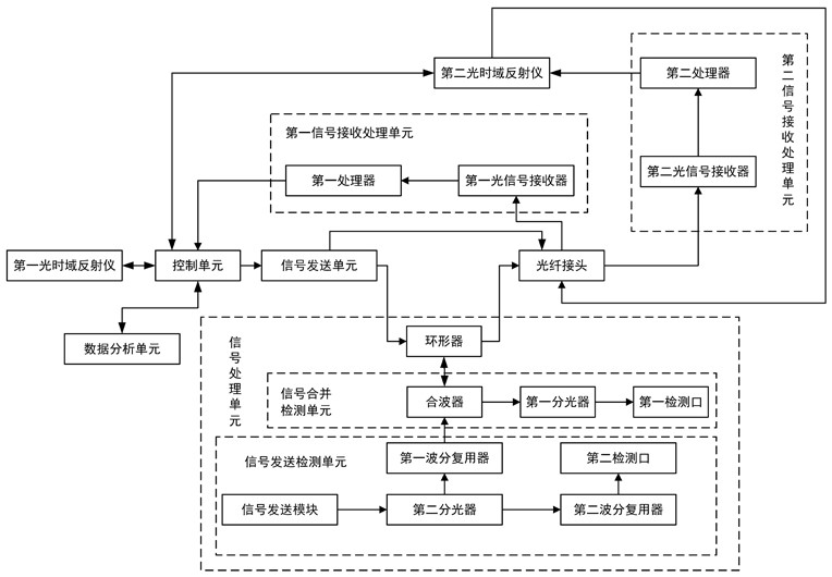
[0038] Embodiment one: as attached figure 1 As shown, the optical cable fault detection device includes a first optical time domain reflectometer, a control unit, a signal sending unit, an optical fiber connector, a first signal receiving and processing unit, a second signal receiving and processing unit, a second optical time domain reflectometer, a data The analysis unit and the signal processing unit; the first optical time domain transmitter, the control unit, the signal sending unit, and the optical fiber connector are connected together in sequence, the first signal receiving and processing unit is respectively connected with the control unit and the optical fiber connector, and the second optical time domain reflection The instrument is respectively connected with the optical fiber connector, the second signal receiving and processing unit and the control unit, the second signal receiving and processing unit is connected with the optical fiber connector, the signal proce...

Embodiment 2

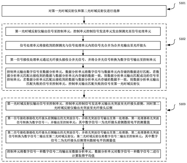
[0057] Embodiment two: as attached figure 2 Shown, a kind of optical cable fault detection method comprises:

[0058] S101, select the first optical time domain reflectometer and the second optical time domain reflectometer;

[0059] S102, if the first optical time domain reflectometer outputs a signal and the second optical time domain reflectometer is turned off, then perform optical cable damage detection, including:

[0060] a, the first optical time domain reflectometer outputs a signal to the control unit, and the control unit controls the signal sending unit to send detection light to the signal processing unit;

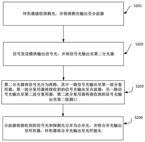
[0061] b. The signal processing unit combines the received detection light and the signal light in the signal processing unit into a combined light output to the optical fiber connector;

[0062] c. The first signal receiving and processing unit receives the combined optical signal through the optical fiber connector, and converts the combined optical signa...


PUM

PropertyMeasurementUnit
lengthaaaaaaaaaa

Abstract

The invention relates to the technical field of optical cable detection, in particular to an optical cable fault detection device and detection method thereof. The optical cable fault detection device comprises a first optical time domain reflectometer, a control unit, a signal sending unit, an optical fiber connector, a first signal receiving and processing unit, a second signal receiving and processing unit, a second optical time domain reflectometer, a data analysis unit and a signal processing unit, wherein the first optical time domain transmitter, the control unit, the signal transmitting unit and the optical fiber connector are sequentially connected together. The optical cable fault detection device is reasonable and compact in structure and convenient to use, the loss of the optical fiber connector is measured by comparing a measured value of the scattering level of the front side of the optical fiber connector with a measured value of the backscattering level of the rear side of the optical fiber connector, the loss of the optical fiber connector is obtained, the phenomenon that the scattering coefficient of the rear side of the optical fiber connector is high is prevented, and the backscattering level of the rear side of the optical fiber connector is greater than the scattering level of the front side of the optical fiber connector, thereby counteracting the loss of the optical fiber connector and causing errors.

Description

technical field [0001] The invention relates to the technical field of optical cable detection, and relates to an optical cable fault detection device and a detection method thereof. Background technique [0002] The detection of long-distance and long-distance optical cables is generally carried out through the optical cable detection system, that is, the detection light source or optical time domain reflectometer plus optical switch is used for detection. The length of the detection optical cable is about 100km ~ 150km. Timely alarm, analyze the cause of the failure in time when a failure occurs. [0003] The optical time domain reflectometer is needed in the construction, maintenance and monitoring of the optical cable. When the optical time domain reflectometer is used to detect the optical fiber connector, due to the high scattering coefficient of the optical fiber at the rear side of the optical fiber connector, the backscattering electricity at the rear side of the op...

Claims


Application Information

Patent Timeline
Patent Type & Authority Applications(China)
IPC IPC(8): H04B10/071
CPCH04B10/071Y04S10/52
Inventor 张强郭庆瑞郭学让何玲李亚平张志军解鹏樊树铭孙勇李春生
Owner ELECTRIC POWER SCI RES INST OF STATE GRID XINJIANG ELECTRIC POWER
Why Eureka
Try Eureka