Backlight driving circuit and display device

A backlight drive circuit and backlight drive technology, applied in static indicators, instruments, etc., can solve the problems of unfavorable wiring and winding equal-length design, insufficient display brightness, affecting display effect, etc., to improve driving effect and ensure display. effect, the effect of increasing the brightness of the light

Active Publication Date: 2022-02-11
KUSN INFOVISION OPTOELECTRONICS
View PDF10 Cites 0 Cited by
  • Summary
  • Abstract
  • Description
  • Claims
  • Application Information

AI Technical Summary

Problems solved by technology

[0006] At the same time, the backlight 110 requires a relatively thin thickness, that is, the number of layers of the backlight 110 is limited, so that the traces on the backlight 110 are integrated on the same layer Structural space is not conducive to the equal-length design of the wiring, so that the length of the driving voltage transmission wiring of multiple light-emitting areas increases with the distance between the light-emitting area and the integrated circuit board 120. The longer the distance, the loss caused by its impedance The larger the value, the smaller the driving voltage corresponding to the light-emitting area, and the smaller the operating current, so that the actual luminous brightness is lower than the ideal design value, and the actual display brightness is insufficient, which affects the display effect

Method used


Image

  • Backlight driving circuit and display device
  • Backlight driving circuit and display device
  • Backlight driving circuit and display device

Examples


Embodiment Construction

[0042] Various embodiments of the invention will be described in more detail below with reference to the accompanying drawings. In the various drawings, the same elements are denoted by the same or similar reference numerals. For the sake of clarity, various parts in the drawings have not been drawn to scale.

[0043] The specific implementation manners of the present invention will be further described in detail below in conjunction with the accompanying drawings and embodiments.

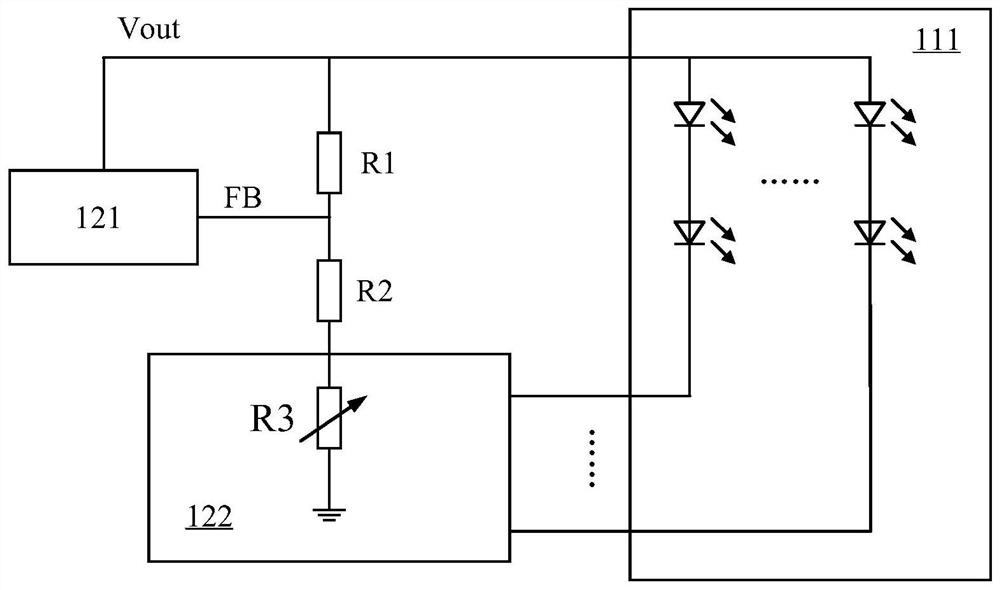
[0044] figure 2 A schematic structural diagram of a backlight driving circuit of a display device according to the prior art is shown, refer to figure 2 , taking a light-emitting area 111 of the backlight panel 110 as an example, the anodes of the light-emitting diode strings in the light-emitting area 111 are interconnected to receive the backlight driving voltage Vout, and the cathodes of each light-emitting diode string are respectively connected to the corresponding current drive ports of t...


PUM


Abstract

The invention relates to the technical field of display, and discloses a backlight driving circuit and a display device.The display device comprises the backlight driving circuit, the backlight driving circuit is provided with a control unit to compare working current of a backlight plate with set current, and when the working current is smaller than the set current, the ratio of the sampling voltage to the backlight driving voltage output by a power supply module is controlled to be reduced, so that the backlight driving voltage output by the power supply module can be improved through a feedback output loop of the power supply module, the driving capability to the backlight plate is improved, the working current of the backlight plate is improved to a set value, and the backlight brightness is adjusted to be consistent with an ideal set value; the display effect is improved.

Description

technical field [0001] The present invention relates to the field of display technology, in particular to a backlight driving circuit and a display device. Background technique [0002] Most of the liquid crystal display devices on the market are backlight type liquid crystal display devices, which include a liquid crystal display panel and a backlight plate. The working principle of the liquid crystal display panel is to pour liquid crystal molecules between the thin film transistor array substrate (Thin Film Transistor Array Substrate, TFT Array Substrate) and the color filter substrate (Color Filter, CF), and apply the driving voltage on the two substrates To control the rotation direction of the liquid crystal molecules to refract the light from the backlight module to produce a picture. [0003] Due to the light-emitting diode (Light-Emitting Diode, referred to as LED) backlight circuit has the advantages of thinness, low power consumption, high luminous efficiency, st...

Claims


Application Information

Patent Timeline
IPC IPC(8): G09G3/34
CPCG09G3/3406
Inventor 蔡浩王维祎李佳
Owner KUSN INFOVISION OPTOELECTRONICS
Why Eureka
Try Eureka