
An automatic clamping device for thin-walled cylindrical parts

A technology of clamping device and thin-walled cylinder, which is applied in the field of parts processing, can solve the problems affecting the yield rate and cutting accuracy, etc., and achieve the effect of ensuring accuracy and stability, ensuring processing accuracy and quality, and good fixing effect

Active Publication Date: 2022-07-01
南京二机齿轮机床有限公司
View PDF0 Cites 0 Cited by
  • Summary
  • Abstract
  • Description
  • Claims
  • Application Information

AI Technical Summary

Problems solved by technology

[0002] There are generally two types of processing of existing thin-walled cylindrical parts. One is the simple combined clamping method. In this method, the parts must be corrected every time the parts are re-clamped to ensure the processing accuracy, which requires manpower and time input; This kind of automatic fixture generally tightens or clamps the centering surface with the expansion sleeve or chuck, and uses the tension or clamping force to fix the parts at the same time. This fixture has a high degree of automation and is suitable for batch processing of parts, but when the parts When the processing part is too deep and too long, the part will swing during the cutting process because the cutting force is greater than the fixing force of the expansion sleeve or the chuck, which will affect the cutting accuracy and affect the yield

Method used


Image

  • An automatic clamping device for thin-walled cylindrical parts
  • An automatic clamping device for thin-walled cylindrical parts
  • An automatic clamping device for thin-walled cylindrical parts

Examples


Embodiment Construction

[0036] The present invention will be more clearly and completely described below by means of a preferred embodiment in conjunction with the accompanying drawings, but the present invention is not limited to the scope of the described embodiments.

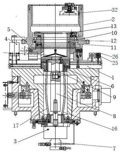
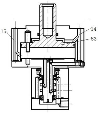
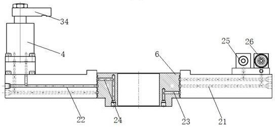
[0037] like Figure 1~Figure 5 Shown is an automatic clamping device for thin-walled cylindrical parts provided by the present invention, including:

[0038] Base 1, set horizontally, supporting thin-walled cylindrical parts 2;

[0039] The hydraulic centering device 3 is vertically arranged in the center of the base 1, and is arranged concentrically with the thin-walled cylindrical part 2, which is used to expand the inner hole of the thin-walled cylindrical part 2, and fix the thin-walled cylindrical part 2 concentrically on the thin-walled cylindrical part 2. Above the base 1;

[0040] The automatic pressing device 4 is arranged on the upper end face of the base 1 and is evenly distributed along the circumferential direction of...


PUM


Abstract

The invention discloses an automatic clamping device for thin-walled cylindrical parts, comprising: a base, which is arranged horizontally and supports the thin-walled cylindrical parts; The concentric setting is used to open the inner hole of the thin-walled cylindrical part, and the thin-walled cylindrical part is concentrically fixed above the base; the automatic pressing device is set on the upper end face of the base, and is uniform along the circumference of the thin-walled cylindrical part. distribution; the side of the thin-walled cylindrical part is provided with an annular boss for matching with the automatic pressing device; the hydraulic oil circuit of the hydraulic centering device is communicated with the oil circuit of the automatic pressing device; The precise design of the jig, which is first tightened and then compressed, solves the problem of part positioning deviation during cutting of the traditional hydraulic sleeve clamp, and has extremely high automation capabilities, which can ensure large-scale and high-precision processing of parts.

Description

technical field [0001] The invention relates to the technical field of parts processing, in particular to an automatic clamping device for thin-walled cylindrical parts. Background technique [0002] There are generally two types of thin-walled cylindrical parts processing. One is a simple combined clamping method. In this method, the parts must be corrected every time the parts are re-clamped to ensure the machining accuracy, which requires the investment of manpower and time; This kind of automatic fixture is generally used to expand the sleeve or chuck to tighten or clamp the centering surface, and use the tightening force or clamping force to fix the parts at the same time. This fixture has a high degree of automation and is suitable for batch processing of parts. When the machining part is too deep and too long, the cutting accuracy will be affected and the yield will be affected by the swing of the parts during the cutting process because the cutting force is greater t...

Claims


Application Information

Patent Timeline
Patent Type & Authority Patents(China)
IPC IPC(8): B23Q3/08B23Q3/06B23B31/40B23Q11/00
CPCB23Q3/082B23Q3/065B23B31/40B23Q11/0042
Inventor 张津赫陶星彭杰
Owner 南京二机齿轮机床有限公司
Learn More