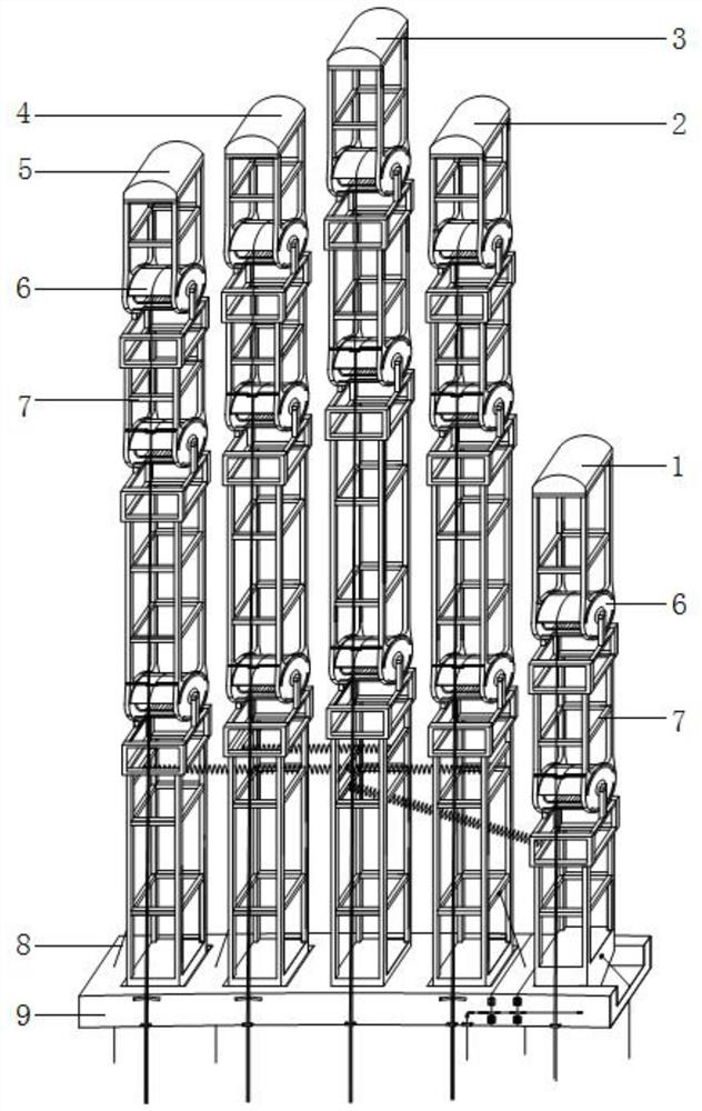
Humanoid robot hand structure
A robot hand and humanoid technology, which is applied in the direction of manipulators, chucks, manufacturing tools, etc., can solve the problems of small degree of freedom and poor flexibility, and achieve the effects of convenient installation and operation, simple control, and improved stability and reliability
- Summary
- Abstract
- Description
- Claims
- Application Information
AI Technical Summary
Problems solved by technology
Method used
Image


Examples
Embodiment 1
[0036] Embodiment 1: Reference Image 6 with Figure 7 As shown, the joint device 6 in the present invention includes a support frame 62 fixedly connected to the phalanx 7, and a running wheel fixedly connected to the adjacent phalanx 7, a support shaft 63 is installed on the support frame 62, and the rotating wheel The wheel includes two side wheel plates 65 and an arc-shaped steel plate 66, the arc-shaped steel plate 66 is connected between the two side wheel plates 65, and the two side wheel plates 65 are provided with coaxial shaft holes and rotate Set on the outer circular surface at both ends of the support shaft 63, the torsion spring 64 is sleeved on the support shaft 63 and is located in the arc-shaped steel plate 66 between the two side wheel plates 65, and the arc-shaped steel plate 66 is provided with joint pull wires 61, by pulling the joint stay wire 61, the runner can be driven to rotate around the support shaft 63, so that the knuckle 7 connected to the runner...
Embodiment 2
[0037] Embodiment 2: Reference Figure 8 with Figure 9 As shown, the joint device 6 in the present invention includes a support frame 62 fixedly connected to the phalanx 7, and a running wheel fixedly connected to the adjacent phalanx 7, a support shaft 63 is installed on the support frame 62, and the rotating wheel The wheel includes two side wheel plates 65 and an arc-shaped steel plate 66, the arc-shaped steel plate 66 is connected between the two side wheel plates 65, and the two side wheel plates 65 are provided with coaxial shaft holes and rotate Set on the outer circular surface at both ends of the support shaft 63, the torsion spring 64 is sleeved on the support shaft 63 and is located in the arc-shaped steel plate 66 between the two side wheel plates 65, and the arc-shaped steel plate 66 is provided with joint pull wires 61, by pulling the joint stay wire 61, the runner can be driven to rotate around the support shaft 63, so that the knuckle 7 connected to the runne...
PUM
 Abstract
Description
Claims
Application Information
 - R&D
- Intellectual Property
- Life Sciences
- Materials
- Tech Scout
- Unparalleled Data Quality
- Higher Quality Content
- 60% Fewer Hallucinations
Browse by: Latest US Patents, China's latest patents, Technical Efficacy Thesaurus, Application Domain, Technology Topic, Popular Technical Reports.
© 2025 PatSnap. All rights reserved.Legal|Privacy policy|Modern Slavery Act Transparency Statement|Sitemap|About US| Contact US: help@patsnap.com