Test device and test method for wear test of filling slurry conveying pipeline

A technology for conveying pipelines and filling slurry, which is applied in the directions of measuring devices, testing wear resistance, and analyzing materials, etc. It can solve the problems of inability to carry out pipeline wear tests, inapplicability, and easy wear of pipelines, so as to achieve efficient and high-quality preparation, prevent Segregation and sedimentation, good test effect

Pending Publication Date: 2021-08-06
CHINA MINMETALS CHANGSHA MINING RES INST
View PDF0 Cites 2 Cited by
  • Summary
  • Abstract
  • Description
  • Claims
  • Application Information

AI Technical Summary

Problems solved by technology

In actual production, there are a large number of horizontal conveying pipelines, and the elbows of the pipelines are more prone to wear, and this test device cannot carry out the pipeline wear test under this working condition
[0005] The prior art also provides a paste-filled horizontal pipeline wear test device, but this test device is only suitable for the experimental research of horizontal pipeline wear, and is not suitable for vertical pipelines and inclined pipelines

Method used


Image

  • Test device and test method for wear test of filling slurry conveying pipeline
  • Test device and test method for wear test of filling slurry conveying pipeline

Examples


Embodiment 1

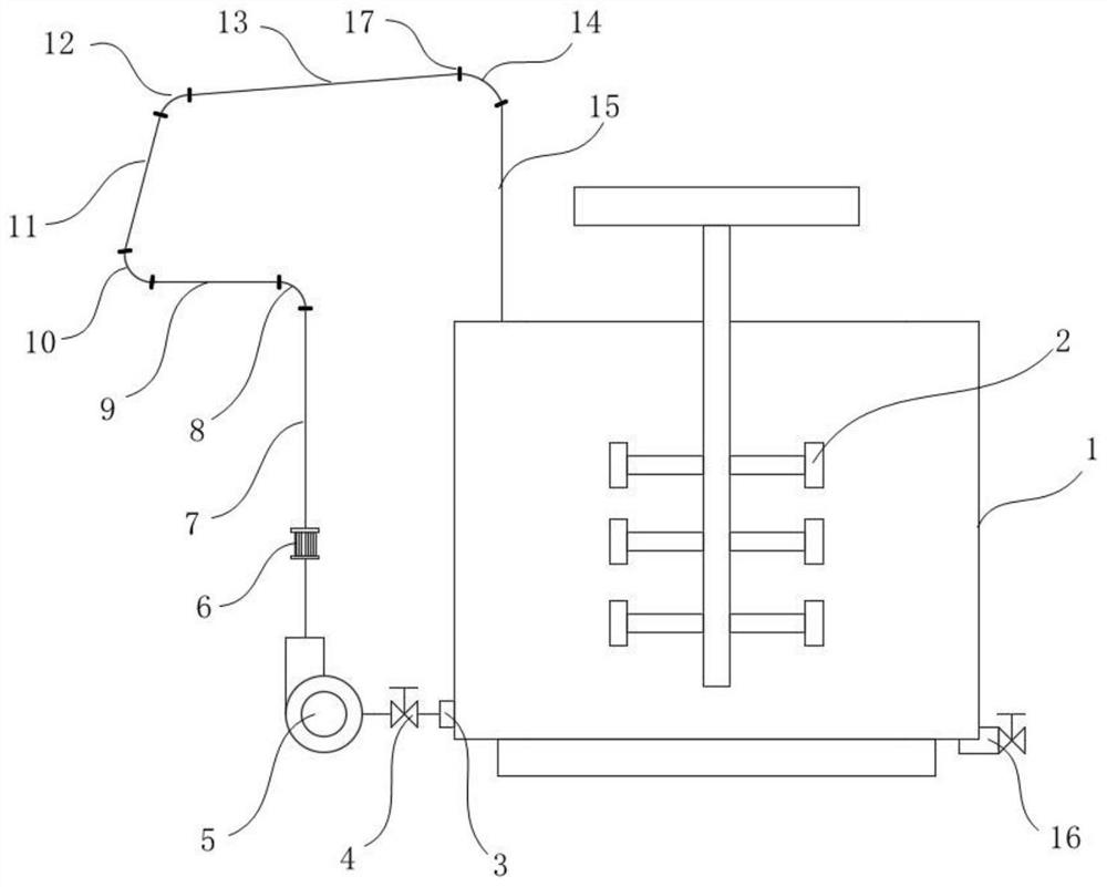
[0038] like figure 1 As shown, a test device for the wear test of the filling slurry conveying pipeline includes a stirring tank 1, a conveying assembly connected to the output end of the stirring tank 1, and a test pipe assembly connected to the output end of the conveying assembly. The test pipe The output end of the assembly is connected to the input end of the stirring tank 1 to recycle the filling slurry, so as to study the wear law of the test pipe assembly with less test material. The conveying component is preferably a frequency conversion slurry pump 5, by controlling the pumping frequency of the frequency conversion slurry pump 5, the research on the pipeline wear of the filling slurry at different flow rates can be realized. The test pipeline assembly includes several interconnected horizontal pipelines 9, elbows, inclined pipelines and vertical pipelines, which can simulate various slurry transportation conditions.

[0039] With such a setting, the research on the...

Embodiment 2

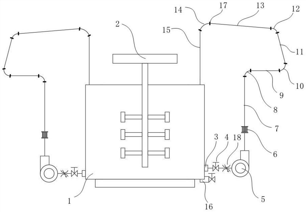
[0062] like figure 2 As shown, in this embodiment, the bottom of the stirring tank 1 is provided with a plurality of outlets 3 . The conveying assembly includes a plurality of frequency conversion slurry pumps 5 respectively connected to the outlet 3 of the stirring tank 1 . Moreover, on-off valves 4 and flow valves 18 are provided on the connecting pipelines between each frequency conversion slurry pump 5 and the stirring tank 1 .

[0063] In this embodiment, the test pipeline assembly includes multiple sets of test pipelines respectively connected to multiple frequency conversion slurry pumps 5 , and each set of test pipelines includes multiple types of delivery pipelines.


PUM


Abstract

The invention discloses a test device and a test method for a wear test of a filling slurry conveying pipeline, and the test device comprises a stirring tank, a conveying assembly connected with the output end of the stirring tank, and a test pipeline assembly connected with the output end of the conveying assembly. The output end of the test pipeline assembly is connected with the input end of the stirring tank; and the test pipeline assembly comprises a plurality of horizontal pipelines, elbows, inclined pipelines and vertical pipelines which are connected with one another. By means of the mode, the abrasion law of filling slurry with different proportions in a horizontal pipeline, an inclined pipeline, a vertical pipeline, an elbow and the like can be studied, the flow and the flow speed of the filling slurry can be controlled so as to simulate various test environments, and the test effect is better.

Description

technical field [0001] The invention relates to the technical field of mine solid waste filling, in particular to a test device and a test method for wear testing of filling slurry conveying pipelines. Background technique [0002] In the mine filling system, the filling pipe plays an important role as the exclusive channel for the filling slurry. The flow of filling slurry in the pipeline will inevitably cause corrosion and friction to the pipeline, causing the filling pipeline to be worn or damaged. At present, many domestic mines using the filling method have encountered the technical problem of serious wear of the filling pipeline. Once the filling pipeline is worn out, it will seriously affect the connection between mine filling and mining procedures, and even affect the normal production of the mine. The study of pipeline wear is of great significance to ensure the safe and stable operation of pipelines. [0003] The prior art provides a device for testing the wear ...

Claims


Application Information

Patent Timeline
Patent Type & Authority Applications(China)
IPC IPC(8): G01N3/56
CPCG01N3/567
Inventor 郑伯坤尹旭岩张宝张凌云尹贤刚彭亮仵锋锋黄腾龙赖伟盛佳邓高岭周贺彬
Owner CHINA MINMETALS CHANGSHA MINING RES INST
Why Eureka
Try Eureka