Power monitoring system and method

A power monitoring and power system technology, applied in information technology support systems, electrical components, circuit devices, etc., can solve the problems of power system security and stability threats, inability to view operations, and emergency measures for power transmission line equipment, etc., to improve management and control Real-time, convenient system supervision, and the effect of reducing inspection costs

Pending Publication Date: 2021-08-06
SHENZHEN HUATONG ELECTRICAL EQUIP CO LTD
View PDF0 Cites 0 Cited by
  • Summary
  • Abstract
  • Description
  • Claims
  • Application Information

AI Technical Summary

Problems solved by technology

The above factors will lead to the aging and fatigue of the components on the line. If the hidden dangers are not discovered and eliminated in time, it may develop into various failures or even accidents, posing a threat to the safety and stability of the power system.
[0003] The inspection and inspection work of transmission lines still stays at the traditional "passive response" level, that is, the line management personnel often obtain the on-site inspection of transmission line equipment through indirect and delayed methods (such as: inspection of personnel in place, notification of line guards, etc.). Therefore, it is impossible to take timely emergency measures for transmission line equipment in some special situations (such as: low temperature icing, sudden mountain fire, etc.)
However, this kind of "behindsight" of hidden dangers in the operation of transmission line equipment has accumulated to a certain extent, which will lead to a series of serious production safety accidents, such as tripping, disconnection, and even tower collapse.
However, the current power monitoring equipment mainly relies on LAN technology to provide information for the background management platform. The information collected by the power monitoring equipment can only be viewed on the specific equipment in the main control room, and can only One-way reception of information collected by power monitoring equipment, unable to view abnormal situations

Method used


Image

  • Power monitoring system and method
  • Power monitoring system and method

Examples


Embodiment Construction

[0040] The following will clearly and completely describe the technical solutions in the embodiments of the present invention with reference to the accompanying drawings in the embodiments of the present invention. Obviously, the described embodiments are only some, not all, embodiments of the present invention. Based on the embodiments of the present invention, all other embodiments obtained by persons of ordinary skill in the art without making creative efforts belong to the protection scope of the present invention.

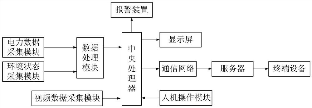
[0041] refer to figure 1 As shown, the present invention discloses a power monitoring system, comprising:

[0042] Central processing unit, power data acquisition module, environmental state acquisition module, data processing module, video data acquisition module, alarm module and man-machine operation module;

[0043] The power data acquisition module is connected to the first input end of the data processing module, and is used to collect voltage parameter...


PUM


Abstract

The invention discloses a power monitoring system and method, and relates to the technical field of power monitoring. The system comprises a central processor, a power data collection module, an environment state collection module, a data processing module, a video data collection module, an alarm module, and a man-machine operation module. The system has a network communication function and can transmit measurement value and semaphore information upwards through a communication network; through visualization, the inspection cost of a power distribution station is greatly reduced, and the control real-time performance and the safety and reliability of the whole system are improved; man-machine operation is realized, and system supervision is facilitated.

Description

technical field [0001] The invention relates to the technical field of electric power monitoring, in particular to an electric power monitoring system and method. Background technique [0002] Transmission lines are an important part of the power system. Due to their long-term exposure to the natural environment, they must not only bear the internal pressure of normal mechanical loads and electrical loads, but also withstand pollution, lightning strikes, strong winds, floods, landslides, subsidence, earthquakes and birds. harm and other external factors. The above factors will lead to the aging and fatigue of the components on the line. If the hidden dangers are not discovered and eliminated in time, it may develop into various failures or even accidents, posing a threat to the safety and stability of the power system. [0003] The inspection and inspection work of transmission lines still stays at the traditional "passive response" level, that is, the line management perso...

Claims


Application Information

Patent Timeline
IPC IPC(8): H02J13/00
CPCH02J13/00002H02J13/00001H02J13/00006H02J13/00034H02J13/00032Y04S10/40Y04S40/12Y02B90/20
Inventor 赵发生
Owner SHENZHEN HUATONG ELECTRICAL EQUIP CO LTD
Why Eureka
Try Eureka