
Control method of single-phase single-stage boost inverter

A control method and single-stage technology, applied in the direction of output power conversion device, AC power input conversion to DC power output, electrical components, etc., can solve problems such as waveform distortion, achieve low voltage stress, avoid output waveform distortion, Practical effect

Active Publication Date: 2021-08-06
NANTONG UNIVERSITY
View PDF9 Cites 0 Cited by
  • Summary
  • Abstract
  • Description
  • Claims
  • Application Information

AI Technical Summary

Problems solved by technology

[0003] In view of this, the present invention proposes a control method for a single-phase single-stage boost inverter, which effectively solves the problem of waveform distortion of the single-phase single-stage boost inverter under light load under the traditional modulation method , has a stronger practicality

Method used


Image

  • Control method of single-phase single-stage boost inverter
  • Control method of single-phase single-stage boost inverter
  • Control method of single-phase single-stage boost inverter

Examples


Embodiment Construction

[0026] The following will clearly and completely describe the technical solutions in the embodiments of the present invention in conjunction with the accompanying drawings in the embodiments of the present invention. Obviously, the described embodiments are only some of the embodiments of the present invention, not all of them. Based on the embodiments of the present invention, all other embodiments obtained by persons of ordinary skill in the art without making creative efforts belong to the protection scope of the present invention.

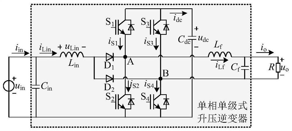
[0027] figure 1 The single-phase single-stage boost inverter shown includes: input voltage source u in , input capacitance C in , input inductance L in , the first anti-reverse diode D 1 , the second anti-reverse diode D 2 , the first switch tube S 1 , the second switch tube S 2 , the third switch tube S 3 , the fourth switch tube S 4 , output filter capacitor C f , Output filter inductance L f and resistive load R; input voltage sour...


PUM


Abstract

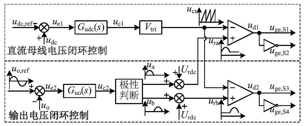
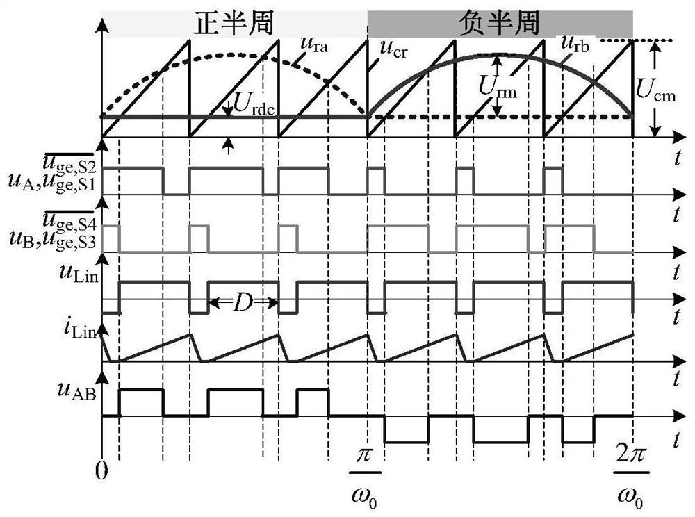
The invention relates to a control method of a single-phase single-stage boost inverter. The control method comprises the steps of obtaining a direct current bus voltage, adjusting the frequency of a unipolar triangular carrier signal through a direct current bus voltage PI controller, and achieving the adjustment of the direct current bus voltage; obtaining output voltage, and achieving output waveform and amplitude control through an output voltage PI controller. Compared with the prior art, the method provided by the invention has the advantages that by changing the control freedom degree of the system, the problem of output waveform distortion caused by large-range boost duty ratio adjustment of the single-phase single-stage boost inverter during light load in a traditional PWM + SPWM modulation mode is effectively avoided, and the practicability is higher.

Description

technical field [0001] The invention belongs to the technical field of inverters, and in particular relates to a control method for a single-phase single-stage boost inverter. Background technique [0002] Since the output voltage of DC power sources such as photovoltaic cells, fuel cells, and storage batteries is low and has a wide range of variation, renewable energy distributed power generation systems generally use a two-stage boost converter cascaded voltage source inverter (VSI) structure. The control of this solution is relatively simple, but the number of power devices is large, the system cost is high, and the efficiency is difficult to further improve. In recent years, some scholars have proposed that the input inductance L in Through two diodes, they are respectively connected to the midpoint of each bridge arm of the single-phase VSI, thereby realizing a single-stage boost inverter. The single-phase single-stage boost inverter usually adopts PWM+SPWM modulatio...

Claims


Application Information

Patent Timeline
IPC IPC(8): H02M7/501H02M7/5387H02M7/5395
CPCH02M7/501H02M7/53871H02M7/5395
Inventor 秦岭沈家鹏张雷段冰莹钱天泓王亚芳许兴周磊田民高娟张振坤
Owner NANTONG UNIVERSITY
Learn More