
Overload automatic lifting speed reducer for settling tank

An automatic lifting and settling tank technology, applied in motor control, electromechanical devices, sediment separation, etc., can solve problems affecting work efficiency, damage to drive motors, large rotating mechanisms, etc., and achieve the effect of avoiding damage and reducing load

Inactive Publication Date: 2021-08-06
杭州阅希电梯销售有限公司
View PDF0 Cites 0 Cited by
  • Summary
  • Abstract
  • Description
  • Claims
  • Application Information

AI Technical Summary

Problems solved by technology

[0005] Aiming at the deficiencies of the prior art, the present invention provides a reducer for a settling tank with overload automatic lifting, which has the advantages of automatic overload lifting and avoiding frequent shutdowns, and solves the problem that the rotating mechanism of the existing settling tank is damaged when there are too many sediments. If the resistance is too large, it is easy to cause the drive motor to be overloaded and damaged. Some reducers for settling tanks with overload protection function will stop running directly when overload occurs, until the overload is removed, which is likely to affect the work efficiency.

Method used


Image

  • Overload automatic lifting speed reducer for settling tank
  • Overload automatic lifting speed reducer for settling tank
  • Overload automatic lifting speed reducer for settling tank

Examples


Embodiment Construction

[0026] The following will clearly and completely describe the technical solutions in the embodiments of the present invention with reference to the accompanying drawings in the embodiments of the present invention. Obviously, the described embodiments are only some, not all, embodiments of the present invention. Based on the embodiments of the present invention, all other embodiments obtained by persons of ordinary skill in the art without making creative efforts belong to the protection scope of the present invention.

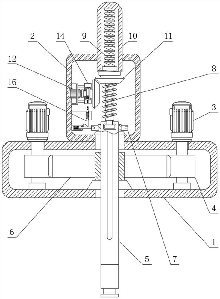
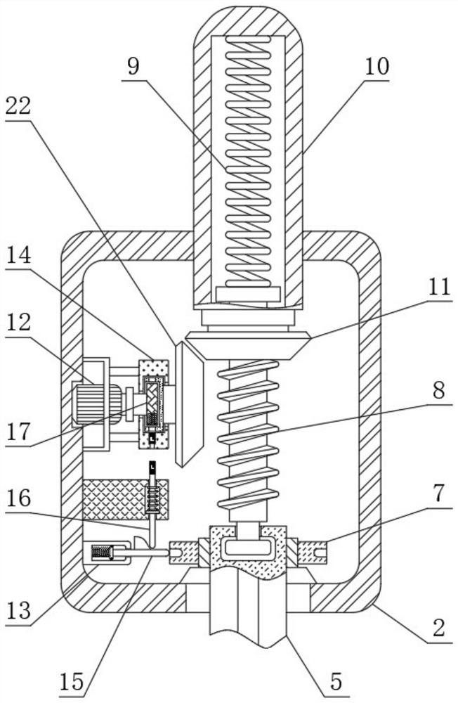
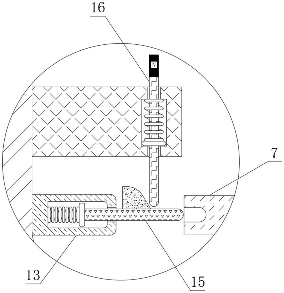
[0027] see Figure 1-6 , a settling tank with overload automatic lifting reducer, including a housing 1, the top of the housing 1 is fixedly connected with a lifting box 2 and two driving motors 3, and the bottom of the two driving motors 3 is connected with a driving gear 4 in rotation , the inner bottom wall of the housing 1 is rotatably connected with a reduction gear 6, the two drive gears 4 are meshed with the reduction gear 6, the number of teeth of the ...


PUM


Abstract

The invention relates to the technical field of speed reducers, and discloses an overload automatic lifting speed reducer for a settling tank. The overload automatic lifting speed reducer comprises a lifting box and a first conical wheel, the inner bottom wall of the lifting box is rotatably connected with a rotating disc, a main shaft is inserted into the rotating disc, and a lifting screw rod is inserted into the top of the main shaft; a lifting motor and a fixing cylinder are fixedly connected to the inner left wall of the lifting box, a driving wheel is rotatably connected to the right side of the lifting motor, a vertical groove is formed in the bottom of the driving wheel, a driven wheel is rotatably connected to the interior of the fixing cylinder, a clamping block is inserted into the bottom of the fixing cylinder, and a second conical wheel is fixedly connected to the right side of the driven wheel. A clamping block is squeezed into a vertical groove, a driving wheel drives a driven wheel to rotate, the driven wheel drives a lifting lead screw to move upwards through a first conical wheel and a second conical wheel, the lifting lead screw drives a main shaft to move upwards, and therefore the effect of automatically lifting overload to reduce the load is achieved, and the situation that a driving motor is damaged due to the overlarge load is avoided.

Description

technical field [0001] The invention relates to the technical field of speed reducers, in particular to a speed reducer for a settling tank with automatic overload lifting. Background technique [0002] The reducer is an independent component composed of gear transmission, worm transmission, and gear-worm transmission enclosed in a rigid shell. It is often used as a reduction transmission device between the prime mover and the working machine. Mechanisms play the role of matching speed and transmitting torque, and are widely used in modern machinery. [0003] The settling tanks used in the non-ferrous metal production industry are generally equipped with a rotating structure, and the rotating mechanism is equipped with a reducer. The rotating mechanism transmits the power to the stirring paddle, and then stirs the sediment at the bottom of the tank. When there is too much resistance to the rotating mechanism, it is easy to cause the drive motor to be overloaded and damaged....

Claims


Application Information

Patent Timeline
Patent Type & Authority Applications(China)
IPC IPC(8): H02P29/028H02P29/032H02K7/06H02K7/10H02K7/116H02K7/14B01D21/28
CPCB01D21/28H02K7/06H02K7/10H02K7/1163H02K7/14H02P29/028H02P29/032
Inventor 陈明位张楚玲
Owner 杭州阅希电梯销售有限公司
Learn More