Automatic obstacle-avoiding mowing equipment
An automatic obstacle avoidance and lawn mowing technology, used in cutters, harvesters, agricultural machinery and implements, etc., to solve problems such as weeds cannot be removed
- Summary
- Abstract
- Description
- Claims
- Application Information
AI Technical Summary
Problems solved by technology
Method used
Image

Examples
specific Embodiment approach 1
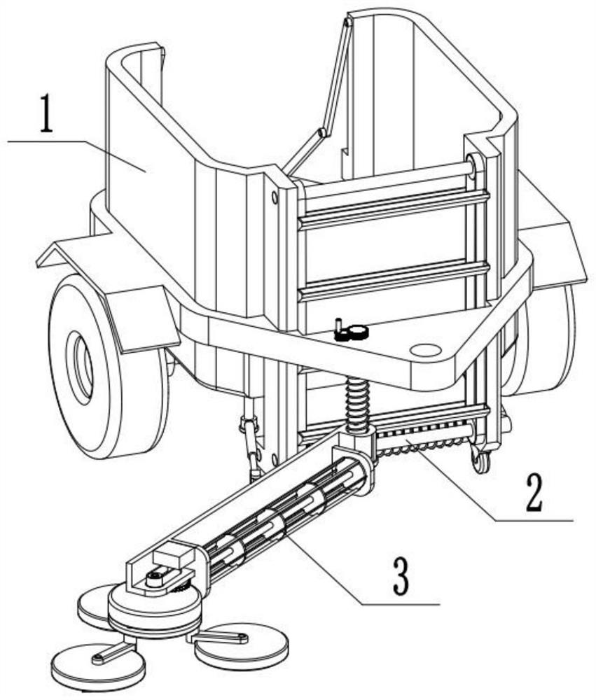
[0032] Combine below Figure 1-16 Describe this embodiment, an automatic obstacle avoidance mowing equipment, including a trailer frame assembly 1, a loading and unloading assembly 2, a lawn mower assembly 3, the trailer frame assembly 1 and the loading and unloading assembly 2 Connected, the trailer frame assembly 1 is connected with the mower assembly 3 .
specific Embodiment approach 2
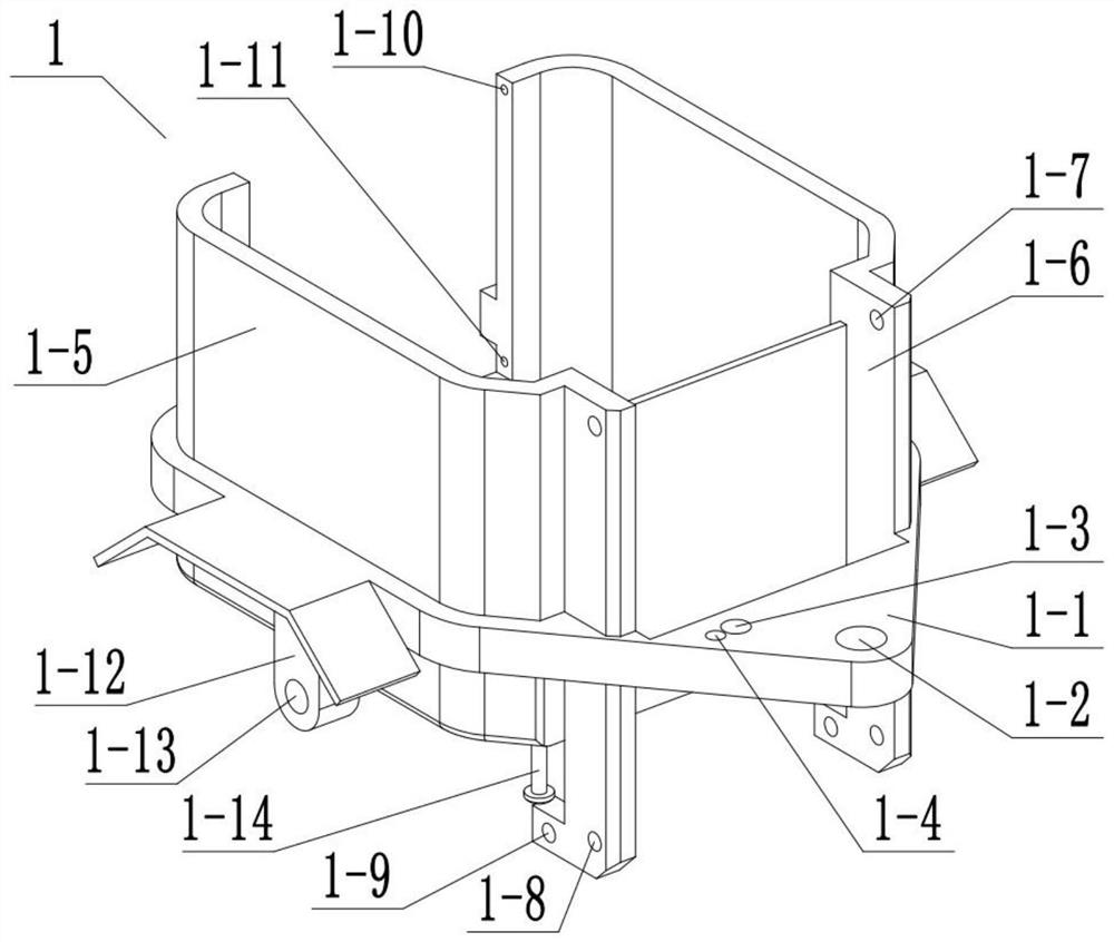
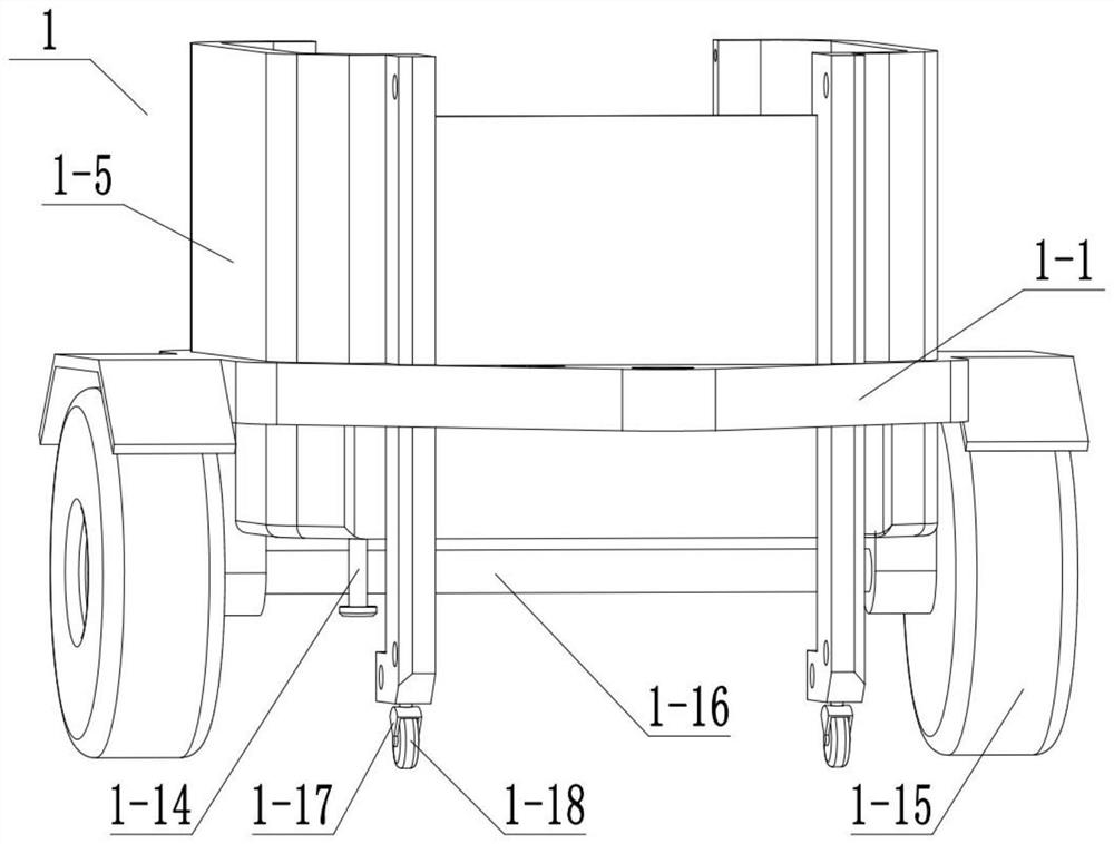
[0034] Combine below Figure 1-16 Describe this embodiment, this embodiment will further explain the first embodiment, the trailer frame assembly 1 includes a frame platform 1-1, a traction connection hole 1-2, a hole 1-3, a hole 2 1-4 , Side wall plate 1-5, connecting plate 1-6, hole three 1-7, hole four 1-8, hole five 1-9, hole six 1-10, hole seven 1-11, axle lug 1-12 , hole eight 1-13, connecting column 1-14, wheel 1-15, axle shaft 1-16, steering wheel frame 1-17, steering wheel 1-18, vehicle frame platform 1-1 is provided with traction connection hole 1- 2. Hole one 1-3, hole two 1-4, the frame platform 1-1 is fixedly connected with the side wall plate 1-5, the connecting plate 1-6, the axle lug 1-12, and the connecting column 1-14, and the side The wall plate 1-5 is fixedly connected with the connection plate 1-6, the side wall plate 1-5 is provided with hole six 1-10, hole seven 1-11, and the connection plate 1-6 is provided with hole three 1-7, hole Four 1-8, five hol...
specific Embodiment approach 3
[0037] Combine below Figure 1-16 Describe this embodiment, this embodiment will further explain Embodiment 1, the described loading and unloading assembly 2 includes a rotating shaft 2-1, a rotating disk 2-2, a rotating shaft 2 2-3, and a rotating disk 2 2-4 , belt one 2-5, hopper 2-6, rotating shaft three 2-7, roller 2-8, belt two 2-9, belt three 2-10, rear wall plate 2-11, connecting rod one 2-12, connecting rod Rod two 2-13, bearing pin 2-14, rotating shaft one 2-1 is fixedly connected with rotating disk one 2-2, rotating shaft one 2-1 is connected with connection plate 1-6 through hole three 1-7 in rotation, rotating disk one 2-2 is connected with rotating disc 2 2-4 through belt 1 2-5, rotating shaft 2 2-3 is fixedly connected with rotating disc 2 2-4, rotating shaft 2 2-3 is connected with connecting plate 1-6 through hole 4 1-8 Rotational connection, belt one 2-5 is fixedly connected with hopper 2-6, rotating shaft three 2-7 is rotationally connected with connecting p...
PUM
 Abstract
Description
Claims
Application Information
 - R&D
- Intellectual Property
- Life Sciences
- Materials
- Tech Scout
- Unparalleled Data Quality
- Higher Quality Content
- 60% Fewer Hallucinations
Browse by: Latest US Patents, China's latest patents, Technical Efficacy Thesaurus, Application Domain, Technology Topic, Popular Technical Reports.
© 2025 PatSnap. All rights reserved.Legal|Privacy policy|Modern Slavery Act Transparency Statement|Sitemap|About US| Contact US: help@patsnap.com