A CNC lathe automatic loading and unloading device

A CNC lathe, forward and backward movement technology, applied in the field of CNC lathes, can solve the problems of large manpower consumption, high labor intensity, complex structure, etc.

Active Publication Date: 2021-09-10
XINXIANG VOCATIONAL & TECHN COLLEGE
View PDF10 Cites 0 Cited by
  • Summary
  • Abstract
  • Description
  • Claims
  • Application Information

AI Technical Summary

Problems solved by technology

[0002] CNC lathes are the most common equipment in mechanical processing. Most of the current CNC lathes rely on manual loading and unloading of workpieces, which has high labor intensity, low efficiency and high cost.
At present, the CNC lathes on the market can realize automatic processing, but the loading and unloading generally requires manual loading and unloading, so it needs to consume a lot of manpower, and the positioning effect is poor during loading, and the existing loading and unloading device has a complicated structure. The effect of taking the workpiece is poor. In the patent CN209174910U, it is only driven by the cylinder and the screw, and controlled by the three directions of X, Y and Z. When processing the workpiece, it is necessary to input a large number of programs inside the controller, and the stability is poor. When grabbing, spatial displacement is required every time to grab, which not only makes the grabbing speed slow, but also has a large error in the position of the workpiece, and cannot accurately control the length of the workpiece inserted into the chuck, resulting in low processing accuracy.

Method used


Image

  • A CNC lathe automatic loading and unloading device
  • A CNC lathe automatic loading and unloading device
  • A CNC lathe automatic loading and unloading device

Examples


Embodiment Construction

[0020] The following will clearly and completely describe the technical solutions in the embodiments of the present invention with reference to the accompanying drawings in the embodiments of the present invention. Obviously, the described embodiments are only some, not all, embodiments of the present invention. Based on the embodiments of the present invention, all other embodiments obtained by persons of ordinary skill in the art without making creative efforts belong to the protection scope of the present invention.

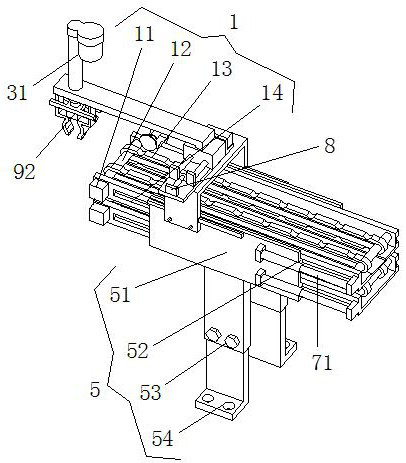
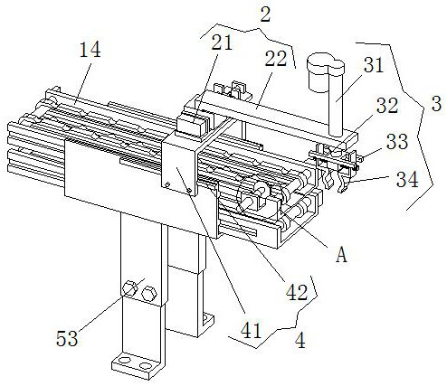
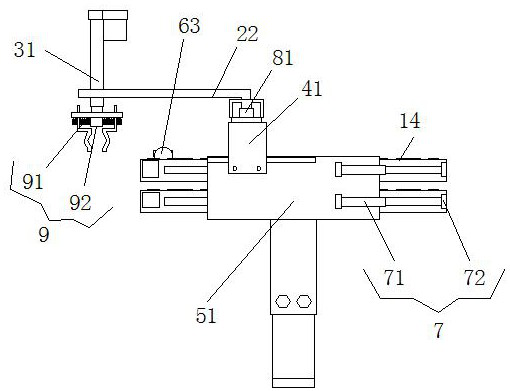
[0021] see Figure 1-5 , the present invention provides a technical solution: an automatic loading and unloading device for a CNC lathe, including a conveying assembly 1, a front and rear moving part 2, a clamping assembly 3, an adjustable support 4, a mounting base 5, a workpiece positioning part 6, a conveying adjustment Part 7, the front and rear positioning parts 8 and the clamping driver 9, the mounting base 5 includes a U-shaped support seat 51, and the ...


PUM


Abstract

The invention discloses an automatic loading and unloading device for a numerical control lathe, which comprises a conveying assembly, a front and rear moving part, a clamping assembly, an adjustable support, a mounting base, a workpiece positioning part, a conveying adjustment part, a front and rear positioning part and a clamping driving part. The installation base includes a U-shaped support seat, and the inner side of the U-shaped support seat is provided with two sets of sliding rails distributed up and down. Conveying components, two conveying components are set up and down, the upper end of the U-shaped support seat is provided with an adjustable support, and the upper surface of the U-shaped support plate of the adjustable support is provided with front and rear moving parts. The rodless cylinder on the upper surface of the type support plate, the automatic loading and unloading device of the CNC lathe, has a simple structure, not only can realize automatic loading and unloading, but also more accurate loading and unloading, making the processed workpiece more accurate.

Description

technical field [0001] The invention relates to the technical field of numerical control lathes, in particular to an automatic loading and unloading device for numerical control lathes. Background technique [0002] CNC lathes are the most common equipment in mechanical processing. Most of the current CNC lathes rely on manual loading and unloading of workpieces, which has high labor intensity, low efficiency and high cost. At present, the CNC lathes on the market can realize automatic processing, but the loading and unloading generally requires manual loading and unloading, so it needs to consume a lot of manpower, and the positioning effect is poor during loading, and the existing loading and unloading device has a complicated structure. The effect of taking the workpiece is poor. In the patent CN209174910U, it is only driven by the cylinder and the screw, and controlled by the three directions of X, Y and Z. When processing the workpiece, it is necessary to input a large ...

Claims


Application Information

Patent Timeline
Patent Type & Authority Patents(China)
IPC IPC(8): B23B15/00
CPCB23Q7/00B23Q7/04
Inventor 程天鹏冯超周欣张雪樊好剑
Owner XINXIANG VOCATIONAL & TECHN COLLEGE
Why Eureka
Try Eureka