Construction method of integrated prefabricated drainage structure for bridge

A construction method and construction technology, applied in the direction of bridges, bridge construction, bridge parts, etc., can solve the problems of high construction design requirements of bridge drain pipes, inconsistent construction quality control on site, and no effective connection measures, so as to avoid main girder diseases , Excellent impact resistance, and the effect of increasing the amount of work

Active Publication Date: 2021-08-10
山西省交通科技研发有限公司
View PDF15 Cites 0 Cited by
  • Summary
  • Abstract
  • Description
  • Claims
  • Application Information

AI Technical Summary

Problems solved by technology

During the operation period, the bridge vibration caused by the vehicle load leads to connection failure or the post-cast concrete is not compacted, so that there are pores between the scupper holes and the drainpipes, so the water on the bridge surface seeps into the bridge flange and web along the pores, and the above parts are generally There are water seepage, efflorescence and other diseases, which seriously reduce the durability of the structure
It can be seen that there are two aspects to the essence of the above-mentioned diseases. One is that there are no effective connection measures between the drain hole and the drain pipe in the design. Failure to take effective measures to block the seepage of water along the crevices

Method used


Image

  • Construction method of integrated prefabricated drainage structure for bridge
  • Construction method of integrated prefabricated drainage structure for bridge
  • Construction method of integrated prefabricated drainage structure for bridge

Examples


Embodiment 1

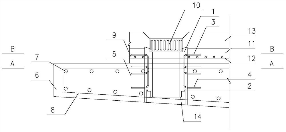
[0025] An integrated prefabricated drainage structure construction method for bridges, comprising the following steps:

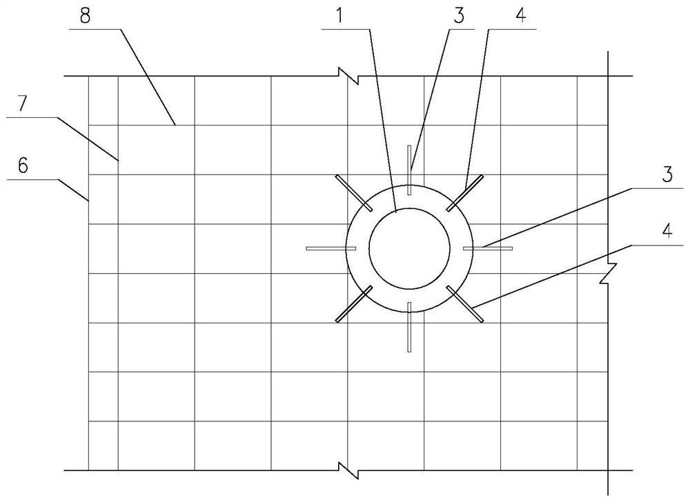
[0026] 1) Prefabricated weep hole drainpipe 1, poured with ultra-high performance concrete, set drip edge 2, drainage pipe fixing device 14, first pre-embedded connecting steel bar 4 and second pre-buried connecting steel bar 3, and drain steel pipe 10 is pre-buried in prefabricated scupper scuppers;

[0027] 2) After the formwork of the main beam flange plate 6 is installed and the longitudinal reinforcement 7 of the main beam flange plate and the hoop 8 of the main beam flange plate are bound, the prefabricated weep hole drain pipe 1 is installed, and the first pre-embedded connecting steel bar 4 is connected to the longitudinal reinforcement of the main beam flange plate. 7 or main beam flange plate stirrup 8 connection, and then pouring main beam concrete;

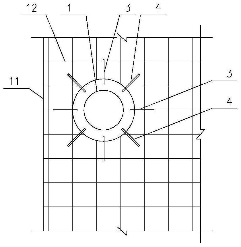
[0028] 3) After laying the reinforced mesh 12 for the concrete bridge deck, weld the second pre-...


PUM


Abstract

The invention discloses a construction method of an integrated prefabricated drainage structure for a bridge. The construction method comprises the following steps that drainage hole drainage pipes are prefabricated, ultra-high performance concrete is adopted for pouring, dripping edges, drainage pipe fixing devices, first pre-buried connecting steel bars and second pre-buried connecting steel bars are arranged, and drainage steel pipes are pre-buried in the prefabricated drainage hole drainage pipes; after a main beam flange plate template is installed and the main beam flange plate longitudinal bars and the main beam flange plate stirrups are bound, prefabricated drain hole drain pipes are installed, the first pre-buried connecting steel bars are connected with the main beam flange plate longitudinal bars or the main beam flange plate stirrups, and then main beam concrete is poured; and after a concrete bridge deck pavement reinforcing mesh is laid, the second pre-embedded connecting steel bars are welded to the reinforcing mesh, then concrete bridge deck pavement is poured, and finally asphalt concrete pavement is poured. According to the integrated prefabricated drainage structure obtained through the construction method, main beam damage caused by water leakage at the drainage holes can be effectively avoided, and the integrated structure facilitates construction and accelerates the progress.

Description

technical field [0001] The invention belongs to the technical field of bridge engineering, in particular to an integrated prefabricated drainage structure construction method for bridges. Background technique [0002] The drain holes and drain pipes are important components of bridge drainage facilities, and are generally arranged outside the side beams. The drain holes and drain pipes are connected by post-cast concrete. There is no connecting piece between the two, and only the concrete Chemically bonded connections. During the operation period, when the bridge vibration caused by the vehicle load causes the connection to fail or the post-cast concrete is not vibrated tightly, there will be pores between the scupper holes and the drain pipes, so the water on the bridge surface will seep into the bridge flange and web along the pores, and the above parts are generally There are diseases such as water seepage and pan-alkali, which seriously reduce the durability of the stru...

Claims


Application Information

Patent Timeline
Patent Type & Authority Applications(China)
IPC IPC(8): E01D19/08E01D21/00
CPCE01D19/086E01D21/00
Inventor 吴佳佳吴焱岳鹏程郭晓澎张天娇申雁鹏赵敏程夏波刘志华李丹梅郭文龙郭震山王磊汪贤安赵雪峰
Owner 山西省交通科技研发有限公司
Why Eureka
Try Eureka