Single-pipe-flow well mouth combination device

A combined device and wellhead device technology, which is applied in wellbore/well valve devices, wellbore/well components, earth-moving drilling, etc. The effect of avoiding shaking and tilting, avoiding corrosion hardness, and ensuring power generation efficiency

Active Publication Date: 2021-08-10
DAQING TIANDEZHONG PETROLEUM SCI & TECH CO LTD
View PDF5 Cites 1 Cited by
  • Summary
  • Abstract
  • Description
  • Claims
  • Application Information

AI Technical Summary

Problems solved by technology

[0002] At present, the most widely known wellhead devices are multi-layer stacked wellhead devices. During the drilling process of this traditional wellhead device, it is necessary to replace blowout preventers of different specifications and perform related operations for each layer installed. It consumes a lot of manpower and materials, has low work efficiency and long cycle. In the existing oil recovery production process, a Christmas tree is installed at the head of the oil well, and various pipelines are controlled by valves to meet the requirements of production. , The valves are installed scattered, occupy a large area, production management is difficult, the workload is heavy, and the phenomenon of oil theft is serious. At present, the process wellhead combination valve is generally used
[0003] In the oil production process of the oilfield, in order to prevent the crude oil flowing through the oilfield wellhead device from sticking or freezing, it is necessary to insulate the pipeline of the oilfield wellhead single-pipe device to ensure the smooth flow of the oil pipeline. External heating type, that is, the method of installing electric heating tape on the pipeline in front of the single-pipe device to ensure the fluidity of the crude oil entering the single-pipe device, so that the crude oil transported will not solidify in the pipeline due to the low temperature. The problem with the method is that it is unsafe, consumes a lot of power, ages quickly, and is not anti-theft

Method used


Image

  • Single-pipe-flow well mouth combination device
  • Single-pipe-flow well mouth combination device
  • Single-pipe-flow well mouth combination device

Examples


Embodiment Construction

[0024] The following will clearly and completely describe the technical solutions in the embodiments of the present invention with reference to the accompanying drawings in the embodiments of the present invention. Obviously, the described embodiments are only some, not all, embodiments of the present invention. Based on the embodiments of the present invention, all other embodiments obtained by persons of ordinary skill in the art without making creative efforts belong to the protection scope of the present invention.

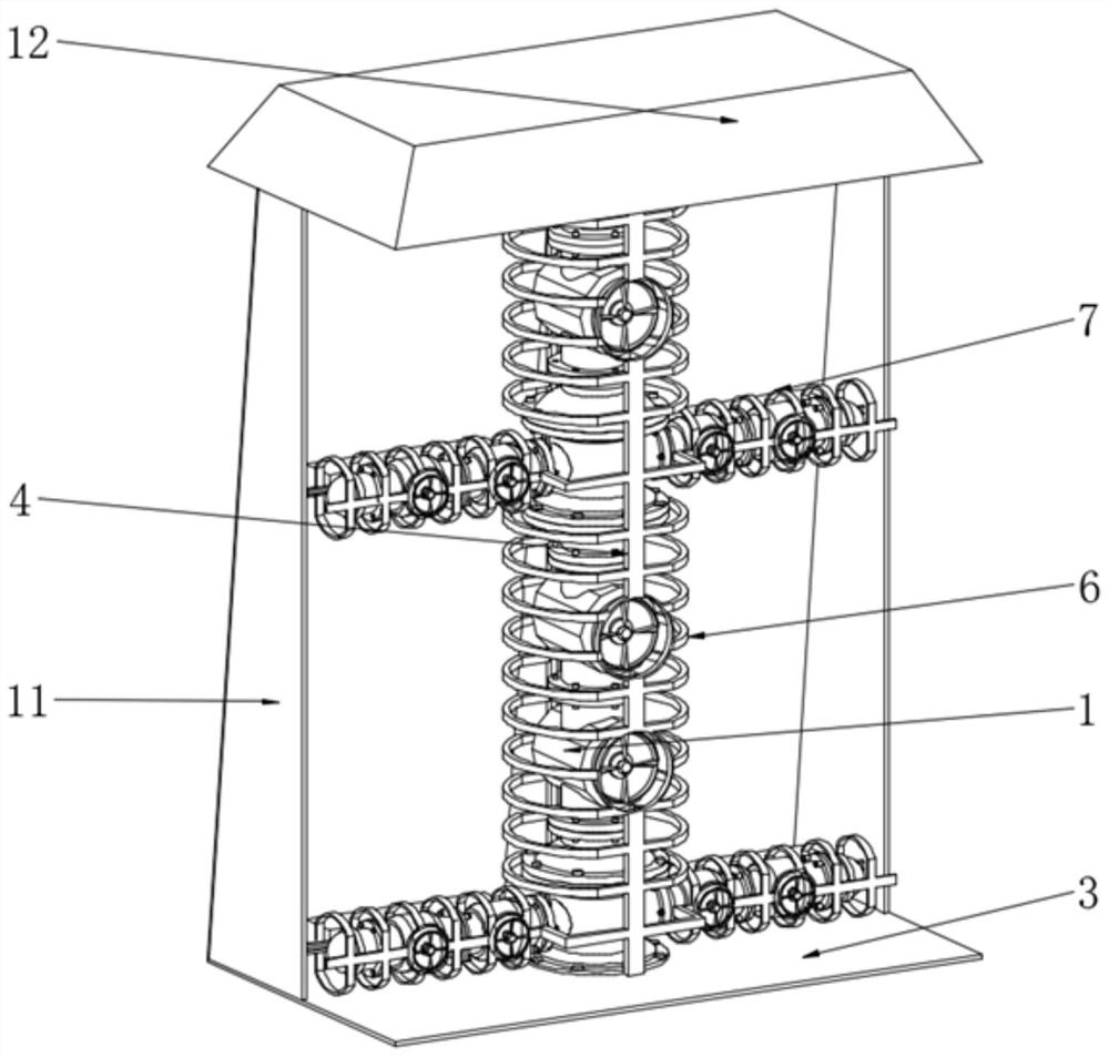
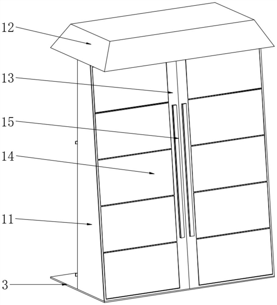
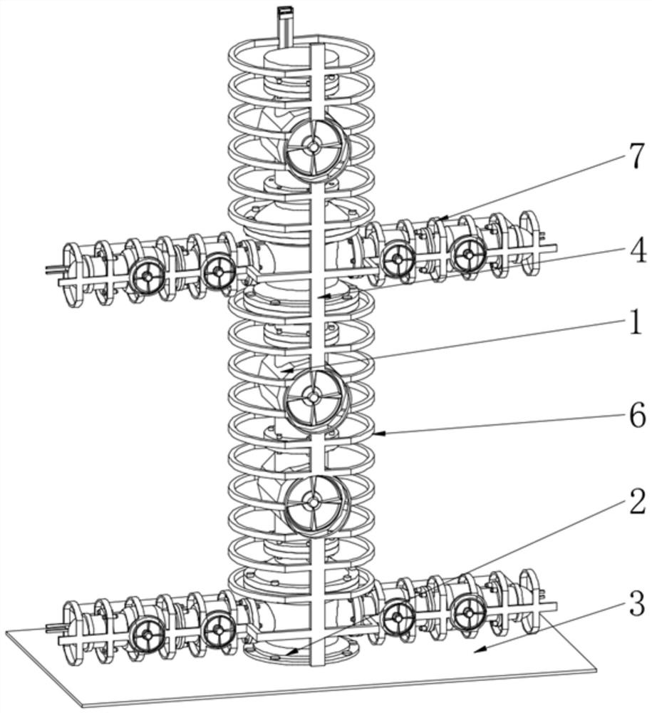
[0025] see Figure 1-6 , a single-pipe process wellhead combination device, including a wellhead device 1, the wellhead device 1 is composed of a total stop valve, a single flow stop valve, a constant pressure release valve, an oil pressure valve, an oil sampling valve, an oil pressure valve and an oil pipe Joints, oil pipe joints and casing joints are connected through flanges. The wellhead device 1 integrates multiple valves and has a novel structure. Each v...


PUM


Abstract

The invention relates to the technical field of oilfield exploitation, and discloses a single-pipe-flow well mouth combination device. The well mouth combination device comprises a well mouth device; a flange plate is fixedly installed at the bottom of the well mouth device; a bottom plate is connected to the outer side of the flange plate in a sleeving mode; and a protection frame is fixedly installed on the middle side of the upper portion of the bottom plate. According to the single-pipe-flow well mouth combination device, the bottom plate is arranged at the bottom of the well mouth device, and the protection frame is arranged on the upper portion of the bottom plate, the middle of the protection frame is provided with a main heat preservation frame and a side heat preservation frame, the main heat preservation frame is located at the trunk position of the well mouth device, and the side heat preservation frame is located at the side branch position of the well mouth device, so that the well mouth device is conveniently protected and supported under the protection of the protection frame, the main heat preservation frame and the side heat preservation frame, and the well mouth device is prevented from shaking and inclining; and the main heat preservation frame and the side heat preservation frame have the heating function, and heat preservation and freezing prevention of the well mouth device are conducted through the heating function of the main heat preservation frame and the side heat preservation frame, so that the well mouth device and an oil pipeline are ensured to be unblocked.

Description

technical field [0001] The invention relates to the technical field of oilfield exploitation, in particular to a single-pipe flow wellhead combination device. Background technique [0002] At present, the most widely known wellhead devices are multi-layer stacked wellhead devices. During the drilling process of this traditional wellhead device, it is necessary to replace blowout preventers of different specifications and perform related operations for each layer installed. It consumes a lot of manpower and materials, has low work efficiency and long cycle. In the existing oil recovery production process, a Christmas tree is installed at the head of the oil well, and various pipelines are controlled by valves to meet the requirements of production. , The installation of various valves is scattered, the floor area is large, the production management is difficult, the workload is large, and the phenomenon of oil theft is serious. At present, the process wellhead combination val...

Claims


Application Information

Patent Timeline
Patent Type & Authority Applications(China)
IPC IPC(8): E21B33/03E21B33/047E21B34/02E21B41/00
CPCE21B33/03E21B33/047E21B34/02E21B41/00E21B41/0021
Inventor 张淞源张虎
Owner DAQING TIANDEZHONG PETROLEUM SCI & TECH CO LTD
Why Eureka
Try Eureka