
A control valve with low energy consumption and high response and its control method

A high-response, low-energy-consumption technology, applied in the direction of the valve's fluid energy absorption device, multi-way valve, valve device, etc., can solve the problems of local oil circuit pressure rise, spool action disorder, spool action delay, etc. , to achieve the effects of reducing fluid pressure loss, reducing fluid flow resistance, and low commutation resistance

Active Publication Date: 2022-03-08
SHANDONG UNIV
View PDF0 Cites 0 Cited by
  • Summary
  • Abstract
  • Description
  • Claims
  • Application Information

AI Technical Summary

Problems solved by technology

[0003] When the oil flows through the spool valve, the size and direction of the oil velocity change, and the sharp change of its momentum will not only cause the pressure of the local oil circuit to rise sharply, resulting in impact noise, but also affect the maneuverability of the spool valve and interfere with The signal causes the movement of the spool to be disordered, thus affecting the stability and reliability of the spool valve
When switching the oil circuit, due to the existence of static friction between the valve core and the valve seat, the action of the valve core will be later than the signal control, resulting in insensitive switching

Method used


Image

  • A control valve with low energy consumption and high response and its control method
  • A control valve with low energy consumption and high response and its control method
  • A control valve with low energy consumption and high response and its control method

Examples


Embodiment 1

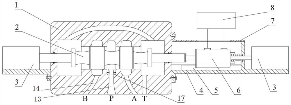
[0041] See how Figure 1-6 , the invention discloses a control valve with low energy consumption and high frequency response, comprising a valve body 1, a valve core 2 is arranged in the valve body 1, one end of the valve core 2 is connected with a first valve core control mechanism 9, and the other end is connected with a rotating motor 6 connections.

[0042] The left and right sides of the valve body 1 are respectively provided with through holes, and the through hole on the left side is used to connect one end of the first spool control mechanism 9 with one end of the spool 2 located in the valve body 1, and the first spool 2 control mechanism 9 Used to control the left and right movement of the spool 2.

[0043] The bottom of the first spool control mechanism 9 is installed on the base 3 , and one end of the base 3 is connected to the side of the valve body 1 . The frame 3 is used to support the first spool control mechanism 9 .

[0044] Such as figure 1 As shown, one...

Embodiment 2

[0067] In the second aspect, the present application also discloses a method for controlling a control valve with low energy consumption and high response, and the specific steps are as follows:

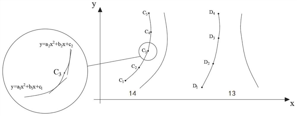
[0068] S1: input the oil into the cavity of the valve body 1 through the first curved channel 13 of the valve body 1;

[0069] S2: The rotary motor 6 drives the spool 2 to rotate;

[0070] S3: The second spool control mechanism 10 moves to the side where the first spool control mechanism 9 is connected to the spool 2 by pushing the rotating motor 6; the first spool control mechanism 9 pushes the spool 2 to the second spool control mechanism The side where 10 is located moves; the oil passes through the second curved channel 14 on the side of the spool 2 close to the first spool control mechanism 9 to control the movement of the actuator connected to the second curved channel 14;

[0071] S4: The first spool control mechanism 9 moves to the side where the second spool control mechani...


PUM


Abstract

The present disclosure relates to the technical field of control valves, in particular to a control valve with low energy consumption and high frequency response. The invention discloses a control valve with low energy consumption and high frequency response, which comprises a valve body, a valve core is arranged in the valve body, one end of the valve core is connected with a first valve core control mechanism, and the other end is connected with an output shaft of a rotating motor; Slidingly connected to the motor seat through the guide rail on the motor seat; the first curved flow channel and the second curved flow channel are arranged on the valve body below the valve core; automatic adjustment is arranged symmetrically on both sides of the first curved flow channel along the horizontal direction The vane group; the self-adjusting vane group includes vanes, the bottom surface of the vane is fixed on the shaft, and the shaft is hingedly connected to the valve body to drive the vane to rotate relative to the valve body; one end of the spring is connected to the vane, and the other end is fixedly connected to the valve body; the valve body The streamlined flow channel is used inside to reduce fluid flow resistance and reduce fluid pressure loss. The spool rotates slowly, with lower commutation resistance, faster response and more sensitive control.

Description

technical field [0001] The present disclosure relates to the technical field of control valves, in particular to a control valve with low energy consumption and high frequency response. Background technique [0002] The reversing valve is a valve that uses the difference in the relative position between the valve core and the valve body to change the on-off relationship of each oil port on the valve body, thereby changing the direction of the liquid flow. [0003] When the oil flows through the spool valve, the size and direction of the oil velocity change, and the sharp change of its momentum will not only cause the pressure of the local oil circuit to rise sharply, resulting in impact noise, but also affect the maneuverability of the spool valve and interfere with The signal causes the movement of the spool to be disordered, thus affecting the stability and reliability of the spool valve. When switching the oil circuit, due to the existence of static friction between the ...

Claims


Application Information

Patent Timeline
Patent Type & Authority Patents(China)
IPC IPC(8): F16K11/07F16K27/04F16K29/00F16K31/04F16K47/02F15D1/00
CPCF16K11/0708F16K27/041F16K29/00F16K31/046F16K47/023F15D1/006
Inventor 谢玉东包木鹏郭卿炜刘延俊
Owner SHANDONG UNIV
Learn More