Distributed intelligent monitoring method and device

A technology of intelligent monitoring and intelligent monitoring system, applied in the direction of character and pattern recognition, data processing applications, instruments, etc., can solve the problems of distributed monitoring of complex circuit environments, expanding the scope of influence of faulty circuits, and evolving into regional circuit faults, etc.

Active Publication Date: 2021-08-10
南京乾鑫电器设备有限公司
View PDF11 Cites 6 Cited by
  • Summary
  • Abstract
  • Description
  • Claims
  • Application Information

AI Technical Summary

Problems solved by technology

[0005] In view of the defects in the prior art, the purpose of the embodiments of the present application is to provide a distributed intelligent monitoring method and device to solve the problem in the prior art that the complex circuit environment cannot be accurately and reliably distributed, so that the nodes The technical problem that a permanent circuit fault may evolve into a regional circuit fault, and then expand the influence range of the faulty circuit, can obtain preliminary analysis results through intelligent monitoring and analysis of arbitrarily selected node circuits, and further, based on the distributed processing unit By processing the analysis results, more accurate processing results can be obtained, and then intermittent monitoring of the obtained processing results is carried out to comprehensively monitor the historical and current circuit data. The system continuously trains the preliminary analysis results and wave recording signals to obtain distributed processing results based on arbitrarily selected node circuits, and then performs power-off processing for abnormal distributed processing results to ensure that the normal operation of other node circuits is not affected. Work, to achieve distributed monitoring of complex circuit environments, to ensure the realization of fault isolation function, so that the intelligent monitoring system has a technical effect of high reliability and stability

Method used


Image

  • Distributed intelligent monitoring method and device
  • Distributed intelligent monitoring method and device
  • Distributed intelligent monitoring method and device

Examples


Embodiment 1

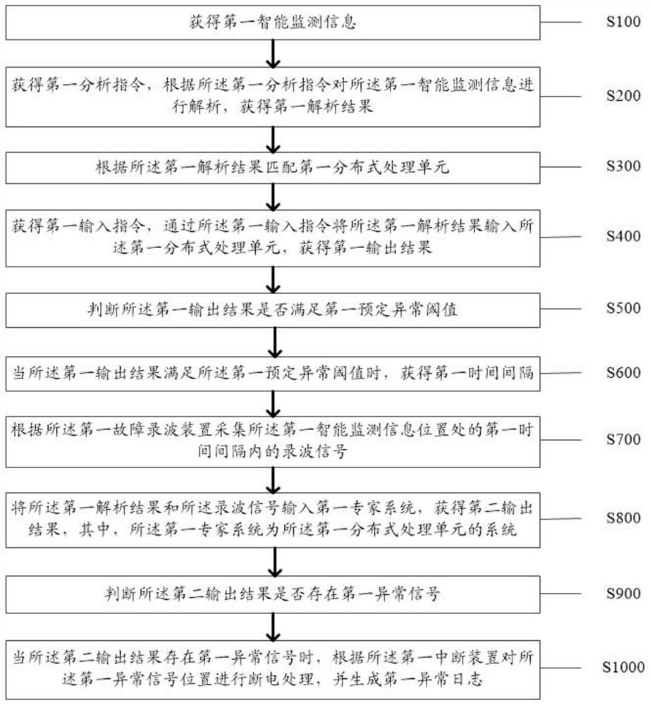
[0025] like figure 1 As shown, the embodiment of the present application provides a distributed intelligent monitoring method, wherein the method is applied to an intelligent monitoring system, and the system is connected in communication with the first fault recording device and the first interruption device, and the method include:

[0026] Step S100: Obtain the first intelligent monitoring information;

[0027]Specifically, as the most common infrastructure in the power system, the power distribution room plays the role of stepping down the high voltage and transmitting it to each household, because the distribution room is usually scattered in location and sealed Mainly, it brings great difficulties to troubleshooting and monitoring. Therefore, the distributed intelligent monitoring of the power distribution room has developed into an important problem to be solved urgently, so as to ensure more efficient intelligent monitoring of the power distribution room. In the emb...

Embodiment 2

[0082] Based on the same inventive concept as the distributed intelligent monitoring method in the foregoing embodiments, the present invention also provides a distributed intelligent monitoring device, such as Figure 4 As shown, the device includes:

[0083] The first obtaining unit 11: the first obtaining unit 11 is used to obtain the first intelligent monitoring information;

[0084] The second obtaining unit 12: the second obtaining unit 12 is configured to obtain a first analysis instruction, analyze the first intelligent monitoring information according to the first analysis instruction, and obtain a first analysis result;

[0085] The first matching unit 13: the first matching unit 13 is configured to match the first distributed processing unit according to the first parsing result;

[0086] The third obtaining unit 14: the third obtaining unit 14 is used to obtain a first input instruction, input the first analysis result to the first distributed processing unit thro...

Embodiment 3

[0124] Refer below Figure 5 An electronic device according to an embodiment of the present application will be described.

[0125] Figure 5 A schematic structural diagram of an electronic device according to an embodiment of the present application is shown.

[0126] Based on the inventive concept of a distributed intelligent monitoring method in the aforementioned examples, the present invention also provides a distributed intelligent monitoring device, on which a computer program is stored, and when the program is executed by a processor, the above-mentioned distributed intelligent monitoring method is realized. The steps of any method of the type intelligent monitoring device.

[0127] Among them, in Figure 5 In, bus architecture (represented by bus 300), bus 300 may include any number of interconnected buses and bridges, bus 300 will include one or more processors represented by processor 302 and various types of memory represented by memory 304 circuits linked toge...


PUM


Abstract

The invention discloses a distributed intelligent monitoring method and device; the method comprises the steps: obtaining first intelligent monitoring information; analyzing to obtain a first analysis result; matching a first distributed processing unit; inputting the first analysis result into a first distributed processing unit to obtain a first output result; judging whether the first output result meets a first preset abnormal threshold value or not; obtaining a first time interval when the condition is satisfied; collecting wave recording signals in a first time interval; inputting the first analysis result and the recording signal into a first expert system to obtain a second output result; judging whether the second output result has a first abnormal signal or not; and when the first abnormal signal position is subjected to power-off processing, generating a first abnormal log. The invention solves the technical problem that in the prior art, accurate and reliable distributed monitoring cannot be carried out on a complex circuit environment, so that a nodal circuit fault can be evolved into a regional circuit fault, and the influence range of a fault circuit is further expanded.

Description

technical field [0001] The invention relates to the technical field of electrical monitoring, in particular to a distributed intelligent monitoring method and device. Background technique [0002] As the most common infrastructure in the power system, the power distribution room plays the role of stepping down the high voltage and delivering it to every household. Because the distribution room is usually scattered in location and mainly in a sealed state, giving Troubleshooting and monitoring present enormous difficulties. Therefore, the distributed intelligent monitoring of the power distribution room has developed into an important problem to be solved urgently, so as to ensure more efficient intelligent monitoring of the power distribution room. [0003] However, in the process of realizing the technical solution of the invention in the embodiment of the present application, the inventor of the present application found that the above-mentioned technology has at least th...

Claims


Application Information

Patent Timeline
Patent Type & Authority Applications(China)
IPC IPC(8): G06F30/27G06K9/62G06Q10/06G06Q50/06
CPCG06F30/27G06Q10/0639G06Q50/06G06F18/24G06F18/214Y02E60/00
Inventor 钱卫华刘小玲
Owner 南京乾鑫电器设备有限公司
Why Eureka
Try Eureka