Control method for dynamically adjusting left-turn special lane and left-turn special phase

A special lane and dynamic adjustment technology, which is applied in the traffic control system of road vehicles, traffic control system, traffic signal control, etc., can solve problems such as long queues, hidden safety hazards, and intersection conflicts, and achieve the effect of improving rationality

Active Publication Date: 2021-08-10
HEFEI UNIV +1
View PDF16 Cites 0 Cited by
  • Summary
  • Abstract
  • Description
  • Claims
  • Application Information

AI Technical Summary

Problems solved by technology

The left-turn special lane and the left-turn special phase are generally set in advance according to the survey of left-turn traffic flow. Since the newly-built intersection does not have historical flow data or the traffic flow of the existing intersection has a dynamic change process, the left-turn traffic flow At intersections that are not large but have clear left-turn requirements and relatively large straight-going traffic, the following problems often exist in the actual application process: First, when the left-turn traffic reaches the required left-turn special phase, no supporting left-turn phase is set. The special lane for turning and the special phase for turning left enable the opposite direction to turn left and go straight to be released at the same time in one signal phase, resulting in a large conflict between going straight and turning left at the intersection, forming a safety hazard and seriously affecting the direction of the intersection release direction The second is that when the left-turn traffic volume does not reach the required left-turn special phase, an unmatched left

Method used


Image

  • Control method for dynamically adjusting left-turn special lane and left-turn special phase
  • Control method for dynamically adjusting left-turn special lane and left-turn special phase
  • Control method for dynamically adjusting left-turn special lane and left-turn special phase

Examples


Embodiment Construction

[0037] The technical solutions in the embodiments of the patent application of the present invention will be clearly and completely described below in conjunction with the drawings in the embodiments of the present invention.

[0038] 1. System equipment installation

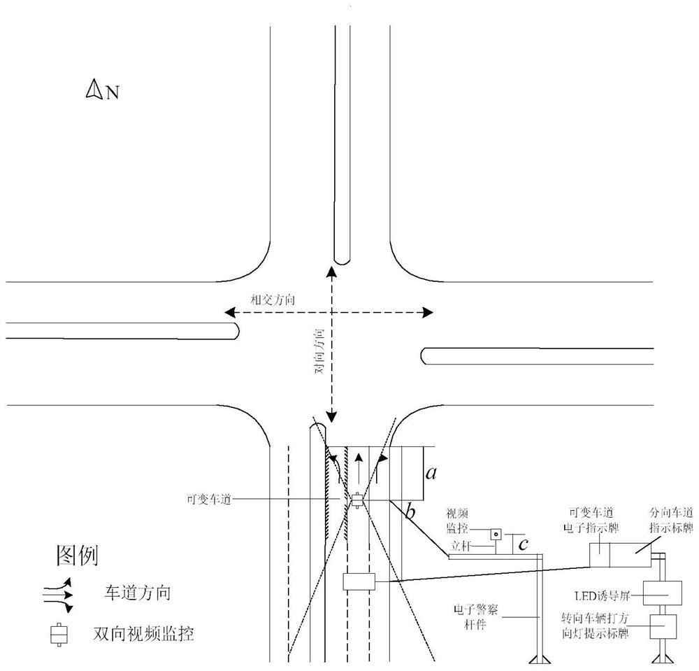
[0039] Such as figure 1 As shown, the main functional components of the system of a control method for dynamically adjusting left-turn special lanes and special phases proposed in this patent application include video surveillance, variable lane electronic signs, diverging lane signage, LED guidance screens, steering Vehicles turn on direction lights and prompt signs and other equipment.

[0040] In this system equipment (taking the south entrance as an example) the video surveillance is installed on the electronic police bar whose distance from the entrance to be tested to the parking line is a (the value range of a is 15-20 meters). The video surveillance adopted in this method For the front detection toward...


PUM


Abstract

The invention discloses a control method for dynamically adjusting a left-turn special lane and a left-turn special phase. The method comprises the following steps: constructing a control system for dynamically adjusting a left-turn special lane and a left-turn special phase at an intersection based on video monitoring, dynamically adjusting acontrol algorithm of the left-turn special lane and the left-turn special phase through variable lane and signal phase setting and variable lane live monitoring, reasonably and dynamically adjusting the setting of the left-turn special lane and the left-turn special phase according to the number, detected by video monitoring equipment in a detection period, of left-turning vehicles of a certain opposite entrance lane and the vehicle flow of each lane, guiding the vehicle to correctly use the variable lane by using a variable lane electronic indication board, combining a LED induction screen to guide the vehicle to correctly use the variable lane, and intelligently controlling the vehicle to pass through an intersection through a traffic signal lamp. The method improves the rationality of the matching design of the lane function and the signal phase at the intersection, reduces the vehicle delay at the intersection, and improves the traffic efficiency.

Description

Technical field: [0001] The invention relates to the field of traffic signal control, in particular to a control method for dynamically adjusting a left-turn special lane and a left-turn special phase. Background technique: [0002] With the increase of urban traffic flow year by year, especially in the central urban area, the phenomenon of intersection congestion is becoming more and more serious, while the land resources of road intersections in the central urban area are becoming increasingly scarce. Under the premise of limited land resources, the optimization of the space-time resources of each lane at the intersection is realized. It is an important research topic to alleviate traffic congestion at urban level intersections. [0003] Left-turn traffic flow is an important consideration in the design of intersection signal phases. Generally, when the left-turn traffic flow of a certain entrance at an intersection is less than 2 to 3 vehicles in a single signal cycle, th...

Claims


Application Information

Patent Timeline
IPC IPC(8): G08G1/07G08G1/081
CPCG08G1/07G08G1/081
Inventor 孔微梁子君肖赟杨军詹学娟吕婷孙培孙倩徐满满吴倩
Owner HEFEI UNIV
Why Eureka
Try Eureka