Novel energy-saving stirrer

An agitator and a new type of technology are applied in mixers with rotary stirring devices, chemical instruments and methods, dissolution and other directions, which can solve the problems of low blade strength, high investment cost, and many molds, and reduce investment costs and production costs. , good circulation effect, the effect of improving efficiency

Pending Publication Date: 2021-08-13
ZHEJIANG HENGFENGTAI REDUCER MFG +1
View PDF1 Cites 0 Cited by
  • Summary
  • Abstract
  • Description
  • Claims
  • Application Information

AI Technical Summary

Problems solved by technology

[0002] The agitator in the stirring mechanical equipment is a key component for forced convection and uniform mixing of fixed, liquid and gas media. The agitator is divided into axial flow agitator and radial flow agitator according to the fluid flow form. The propulsion agitator is the axial flow agitator. The representative of the flow type and circulation type agitator, the blade of the traditional propulsion agitator is similar to the "racket" shape. When it rotates at high speed, the axial suction effect generated by the central part of the blade is undoubtedly the largest, and the tip of the blade shrinks sharply. The energy separation layer is formed, resulting in a state of poor stirring effect. The root of the blade is narrow, and the axial suction effect of the blade root due to high-speed rotation is the smallest, but the torsion and thrust that can be tolerated here are the largest, resulting in the traditional propulsion. The root of the agitator blade has low strength and is easy to break. At present, the traditional propulsion type agitator blade uses many molds in the manufacturing process. It is difficult to make it detachable, the investment cost is large, and the production cost remains high.

Method used


Image

  • Novel energy-saving stirrer
  • Novel energy-saving stirrer
  • Novel energy-saving stirrer

Examples


Embodiment 1

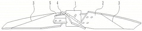
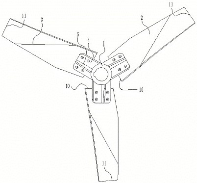
[0028] Embodiment 1: The stirring blade is welded and fixed on the side wall of the hub, that is, the hub and the stirring blade are integrated.

Embodiment 2

[0029] Embodiment 2: A connecting plate is welded and fixed on the side wall of the hub, and the stirring paddle is detachably fixed on the connecting plate.

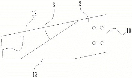
[0030] A bending starting line is provided from the front end of the front side of the blade to the rear end of the rear side of the blade, and the stirring paddle is bent along the starting line of bending, and the starting line of bending is in front of the blade The starting point of the side is located at the rear side of the blade end, and the distance is 0 to 0.1 times the diameter of the agitator. Less than the outer end of the connecting plate 4 as a benchmark.

[0031] A reinforcing rib is provided on the non-liquid-facing surface of the connecting plate, and the reinforcing rib is welded on the hub to improve the overall strength.


PUM


Abstract

The invention discloses a novel energy-saving stirrer. A variable angle is arranged for each blade tip, and each blade is composed of a blade tip, a blade root and an shaped arc, so that a fluid is less sheared. In order to achieve a uniform shaft suction effect along the whole length and obtain the optimal speed effect at each point on the stirring blades, the dip angle and the curved surface chord width along the length direction of the stirring blades are variable, the blade root with lower linear speed is wide and has large dip angle, and the blade tip with higher linear speed is narrow and has small dip angle. The rear sides of the blades are in smooth arc transition, so that the whole stirring blades are streamlined, the curved surfaces of the stirring blades face downwards, an efficient downward suction effect is generated with the minimum pushing force, and finally, smooth motion of a fluid medium is obtained. Meanwhile, separation of a boundary layer with energy loss is prevented, the flow pattern of fluid is in a W shape, and the power consumption is reduced while the flow is maximized. The stirrer has the advantages of high efficiency, energy conservation, consumption reduction, large liquid discharge amount, good circulation effect and simple structure.

Description

technical field [0001] The invention belongs to the technical field of stirring machinery, and in particular relates to a novel energy-saving stirrer. Background technique [0002] The agitator in the stirring mechanical equipment is a key component for forced convection and uniform mixing of fixed, liquid and gas media. The agitator is divided into axial flow agitator and radial flow agitator according to the fluid flow form. The propulsion agitator is the axial flow agitator. The representative of the flow type and circulation type agitator, the blade of the traditional propulsion agitator is similar to the "racket" shape. When it rotates at high speed, the axial suction effect generated by the central part of the blade is undoubtedly the largest, and the tip of the blade shrinks sharply. The energy separation layer is formed, resulting in a state of poor stirring effect. The root of the blade is narrow, and the axial suction effect of the blade root due to high-speed rota...

Claims


Application Information

Patent Timeline
Patent Type & Authority Applications(China)
IPC IPC(8): B01F7/18
CPCB01F27/90
Inventor 陈云才王汉伟杜佐寅李连星
Owner ZHEJIANG HENGFENGTAI REDUCER MFG
Why Eureka
Try Eureka