Rolling shaft type heating device for spinning

A heating device and roller technology, which is used in textile processing machine accessories, processing textile material rollers, textiles and papermaking, etc., can solve the problems of inability to remove cloth debris in time, the cloth cannot be reciprocated, and the impact of subsequent use of the cloth. , to achieve the effect of improving the drying effect, improving the drying effect and avoiding the cost

Active Publication Date: 2021-08-13
南通高隆纺织科技有限公司
View PDF7 Cites 0 Cited by
  • Summary
  • Abstract
  • Description
  • Claims
  • Application Information

AI Technical Summary

Problems solved by technology

[0003] Although the above-mentioned invention can heat and dry both sides of the cloth during use, the above-mentioned invention can only rewind the material through the rewinding roller on one side, so that the whole device can only rewind the cloth once, so that the cloth cannot be obtained. The reciprocating winding allows the cloth to be fully heated and dried by the electric heating tube, which in turn makes the drying effect of the cloth poor, and the above-mentioned invention cannot remove the cloth debris that may adhere to the cloth in time during the use of the cloth. Subsequent use has an impact

Method used


Image

  • Rolling shaft type heating device for spinning
  • Rolling shaft type heating device for spinning
  • Rolling shaft type heating device for spinning

Examples


Embodiment 1

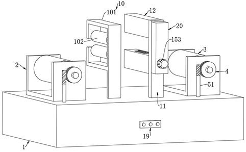
[0027] Such as Figure 1-5 As shown, a roller-type heating device for textiles includes a support platform 1, two brackets 2 are fixedly connected to the support platform 1, and retractable rollers 3 are rotatably connected to the two brackets 2. The rollers 3 are coaxially fixedly connected with the first worm gear 4 , the supporting platform 1 is hollow, and the supporting platform 1 is provided with a transmission mechanism 5 matched with the first worm gear 4 .

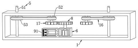
[0028] The transmission mechanism 5 includes a first worm 51, a first synchronous wheel 52 and a second synchronous wheel 53, the first worm 51 is rotatably arranged in the support table 1, and the upper end of the first worm 51 passes through the support table 1 and is connected to the corresponding first The worm gear 4 is meshed, the second synchronous wheel 53 is sleeved on the first worm 51, the first synchronous wheel 52 is rotatably arranged in the support table 1, and the synchronous belt 16 is passed betw...

Embodiment 2

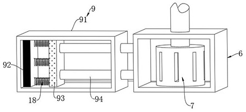
[0038] for Figure 6 The second embodiment shown is different from the first embodiment in that two T-shaped gear bars 23 are slidably connected in the dust removal box 12, and a plurality of stretching rods are fixedly connected between the upper end of the T-shaped gear rods 23 and the dust removal box 12. Spring 24, and the lower end of T-shaped gear bar 23 is fixedly connected with vibrating ball 25, and the incomplete gear 26 that is meshed with T-shaped tooth bar 23 is sleeved on the second worm screw 141, through the T-shaped tooth bar 23 that is set, pull The mutual cooperation of the extension spring 24 and the incomplete gear 26 enables the T-shaped gear rod 23 to cooperate with the rotation and reciprocating sliding of the second worm 141, so that the T-shaped gear rod 23 can drive the vibrating ball 25 to strike the cloth back and forth, causing the cloth to vibrate. And then make the cloth scraps that may adhere on the cloth be vibrated, so that the suction fan 13...


PUM


Abstract

The invention belongs to the field of heating devices for spinning, and particularly relates to a rolling shaft type heating device for spinning. The device comprises a supporting table; two supports are fixedly connected to the supporting table; winding and unwinding rolling shafts are rotatably connected to the two supports; the two winding and unwinding rolling shafts are coaxially and fixedly connected with first worm wheels; the supporting table is designed to be hollow; a transmission mechanism matched with the first worm wheels is arranged in the supporting table; a driving box is slidably connected inside the supporting table; and a driving motor is arranged in the driving box. According to the invention, cloth can be wound in a reciprocating mode, so that while the stretching flatness of the cloth is improved, the cloth can be fully heated and dried by two electric heating rollers, and the cloth drying effect is greatly improved; and meanwhile, the device can clean cloth scraps possibly attached to the two faces of the cloth in time while drying the cloth, so that the later use of the cloth is prevented from being influenced.

Description

technical field [0001] The invention belongs to the field of heating devices for textiles, in particular to a roller heating device for textiles. Background technique [0002] In the process of textile processing, it is often necessary to clean the cloth, and the cleaned cloth needs to be heated and dried. The existing patent (notification number: CN210314853U) is a drying device for automatic textile machinery, including a box. The inside of the box is equipped with parallel The discharge roller and the receiving roller are set, and the rear end surface and the front surface inside the box are distributed and connected with brackets near the center, and several evenly arranged electric heating tubes are installed between the two brackets at the same height... At the back of the box A deceleration motor is installed on the end face, and the output end of the deceleration motor runs through the rear end face of the box body and is connected with the connection plate. The oute...

Claims


Application Information

Patent Timeline
Patent Type & Authority Applications(China)
IPC IPC(8): D06B15/00D06G1/00D06B23/04D06B23/02
CPCD06B15/00D06B23/02D06B23/028D06B23/04D06G1/00
Inventor 吕高建
Owner 南通高隆纺织科技有限公司
Why Eureka
Try Eureka