Device for drying footwear

A drying device and footwear technology, which is applied to household cleaning devices, cleaning and application of boots and shoes, etc., can solve the problems of shortened service life, low heat utilization rate, low drying efficiency of shoes, etc. High utilization rate and good drying effect

Inactive Publication Date: 2011-10-26
GUANGDONG MIDEA ELECTRIC APPLIANCES CO LTD
View PDF5 Cites 0 Cited by
  • Summary
  • Abstract
  • Description
  • Claims
  • Application Information

AI Technical Summary

Problems solved by technology

Over time, the shoes will be deformed, glued (threads), broken, and the shoes will be "rotten", which greatly shortens the service life of the shoes. At the same time, the growth of bacteria in the shoe cavity will not only cause people to wear uncomfortable, but also affect people's health
[0003] At present, people generally use sun exposure, wind blowing or natural drying to dry the inside of shoes. Because the inside of the shoes is deep, the air flow is difficult, and it takes 1-3 days to dry in fine weather. If the temperature is low , the inner cavity of the shoe is difficult to dry, which is a headache
In order to wear dry and comfortable shoes, some people use desiccant to dry the inner cavity of wet shoes. This method is not efficient and troublesome to use.
There are also people who use electric heating wires and baking lamps to dry the damp inner cavity of shoes. This method is not easy to control the drying temperature, and it is easy to damage the shoes. It is not safe to use.
Chinese Patent Application No. 00230137.7 discloses a drying device for shoe chambers, which uses a blower in the chamber to pass the hot air heated by the electric heating element in the chamber through a plurality of through holes on the lower wall of the two chambers Blow into the shoe cavity to dry the shoe cavity. In this way, the gas in the cavity is blown into the shoe cavity by the blower. Since the air outlet in the shoe is in contact with the shoe, the contacted shoe cavity will be blocked. Air ducts are installed, which makes some air ducts have a large air volume, and some places have little or no air output, resulting in uneven heating and drying
At the same time, since the channel in the inner cavity of the shoe has a certain length, the heated air will mostly be blown out from the part with the least wind resistance, while the innermost distance of the shoe is the largest, making the innermost wet part of the shoe the most difficult part to dry. The heat utilization rate is low, resulting in low drying efficiency and poor drying effect

Method used


Image

  • Device for drying footwear
  • Device for drying footwear
  • Device for drying footwear

Examples


Embodiment 1

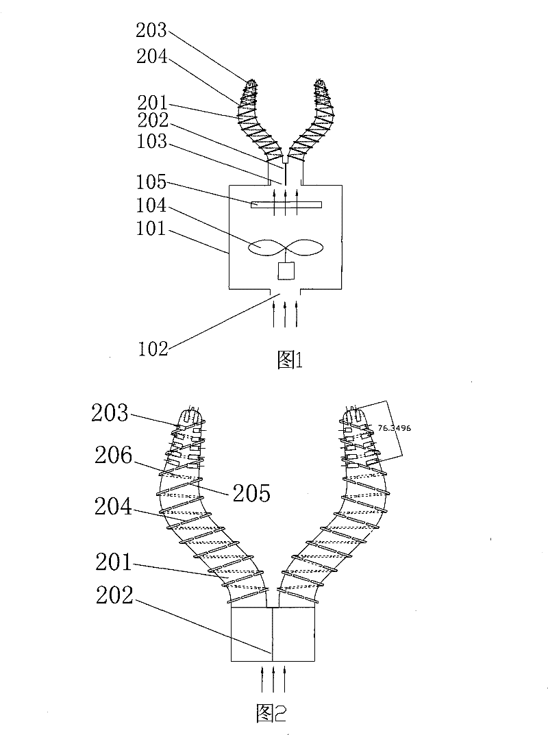
[0040] Embodiment 1 is a form of shoe body bracket with good air duct characteristics and excellent heating and drying performance. Due to the use of spiral air ducts, air circulates in the channel between the outer surface of the shoe body and the inner surface of the shoe cavity. It flows through, so that the hot air can heat the shoe cavity more fully and evenly, and it is far better than the form of comprehensive air supply on the sole for discharging the same amount of humidity or achieving the same humidification effect, such as Figure 5 , the ordinate is the highest water vapor partial pressure in the shoes, and the abscissa is the drying time. The heating curve by adopting the comprehensive air supply form of the sole is I, and the heating and drying curve adopting embodiment 1 is II. As can be seen from this figure, In the initial stage of heating, the humidity in the shoes is the same, and curve I reaches the water vapor partial pressure P0 that is considered dry thr...

Embodiment 2

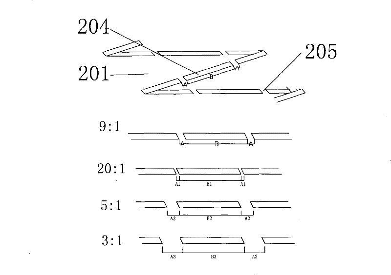
[0043] In this embodiment, the length of the air outlet part accounts for 1 / 6 of the length of the shoe body bracket. Compared with Embodiment 1, the range of the air outlet is reduced, and the wind speed of the air outlet is relatively increased, but the air volume is reduced; The ratio of the length to the interval length is B1:A1=20, the air leakage is small, and the wind speed in the air duct is high; the angle θ1 between the air duct surrounded by the long strip support points and the vertical direction is 103 degrees, and the wind direction is clockwise , the number of turns of the air duct rotation is large, and the wind speed at the air outlet is small. Due to the long flow of the air duct, only a small air volume is needed to meet the drying demand, the power requirements for the fan and the air heater are small, and the drying efficiency is high, which is a preferred embodiment suitable for home use.

Embodiment 3

[0045] In this embodiment, the length of the air outlet part accounts for 2 / 5 of the length of the shoe body bracket. Compared with Embodiment 1, the scope of the air outlet has been expanded, and the air outlet speed has been relatively reduced, but the air volume has increased; The ratio of the length to the interval length is B2: A2 = 5 to B3: A3 = 3, the air leakage volume gradually increases, and the mixed flow in the air duct appears; the angle θ3 between the air duct surrounded by the long strip support points and the vertical direction is 52 degrees, the number of turns of the air duct rotation is less, and the air flow is smoother. It is suitable for commercial applications with relatively large drying capacity and high temperature and humidity requirements.


PUM


Abstract

The invention discloses a drying device for shoes, which comprises an air heater, a fan, an air heating element and at least one shoe holder, wherein the inside of the air heater is provided with the fan for drawing air from an air heater air intake into the inside of the air heater and the air heating element for heating the air to generate hot air, the air heater air outlet of the air heater is communicated with an shoe holder air inlet arranged on the shoe holder, and the shoe holder comprises at least one shoe holder air outlet positioned on the front end of the shoe holder; and the outer surface of the shoe holder is provided with a shoe holder surface supporting point allowing a channel for ventilation to be formed between the outer surface of the shoe holder and the inner wall of ashoe. The device facilitates the uniform flow of hot air in the shoe, avoids the sole and the inner upper of the shoe blocking the air outlet and, at the same time, allows the hot air to pass through the walls of the innermost cavity and the outer cavity of the shoe to dry and sterilize the innermost and outer parts of the shoe uniformly. As the supporting point is relatively small, heat convection of the surrounding hot air can fully dry the wall, supported by the supporting point, of the inner cavity.

Description

technical field [0001] The invention is a drying device for footwear, which belongs to the transformation technology of the drying device for footwear. Background technique [0002] People make the inner cavity of the worn shoes damp due to cleaning shoes or sweating in daily life, though through a night of wind airing, the shoe cavity will not be completely dry. If you wear the same pair of shoes for a few days, the moisture inside the shoes will become more and more serious, and the anaerobic bacteria in the shoes will multiply in large numbers, and the sour smell will be produced due to the rancidity of the bacteria. Over time, the shoes will be deformed, glued (threads), broken, and the shoes will be "rotten", which greatly shortens the service life of the shoes. At the same time, the growth of bacteria in the shoe cavity will not only cause people to wear uncomfortable, but also will affect people's health. [0003] At present, people generally use sun exposure, wind ...

Claims


Application Information

Patent Timeline
Patent Type & Authority Patents(China)
IPC IPC(8): A47L23/20
Inventor 殷飞平刘阳刘艳涛曾祥兵
Owner GUANGDONG MIDEA ELECTRIC APPLIANCES CO LTD
Why Eureka
Try Eureka