Engine air inlet control system and method

A control system and engine technology, applied in the direction of engine control, electrical control, engine components, etc., can solve the problems of inability to monitor and control the actual air intake of the engine, low engine working efficiency, etc.

Active Publication Date: 2021-08-13
WUHAN FINEMEMS
View PDF15 Cites 0 Cited by
  • Summary
  • Abstract
  • Description
  • Claims
  • Application Information

AI Technical Summary

Problems solved by technology

[0004] The main purpose of the present invention is to provide an engine air intake control system and method, aiming to solve the technical probl

Method used


Image

  • Engine air inlet control system and method
  • Engine air inlet control system and method
  • Engine air inlet control system and method

Examples


Embodiment Construction

[0061] It should be understood that the specific embodiments described here are only used to explain the present invention, not to limit the present invention.

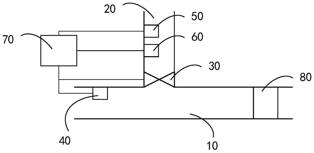
[0062] refer to figure 1 , figure 1 It is a structural block diagram of the first embodiment of the engine air intake control system of the present invention.

[0063] In this embodiment, the engine air intake control system includes: an intake pipe 10, an intake branch 20, a control valve 30, a temperature sensor 40, a heater 50, a cooler 60 and a controller 70;

[0064] The intake pipeline 10 communicates with the intake port 80 of the engine, the intake branch 20 communicates with the intake pipeline 10 through the control valve 30 , and the temperature sensor 40 is arranged on the intake pipeline 10 At the entrance of , the heater 50 and the desuperheater 60 are arranged in the intake branch 20 , the controller 70 is connected with the control valve 30 , the heater 50 , the desuperheater 60 and the The temperat...


PUM


Abstract

The invention discloses an engine air inlet control system and method. The system comprises an air inlet pipeline communicated with an air inlet of an engine, an air inlet branch communicated with the air inlet pipeline through a control valve, a temperature sensor arranged at an inlet of the air inlet pipeline, a heater, a cooler and a controller connected with the control valve, the heater, the cooler and the temperature sensor, wherein the heater and the cooler are arranged in the air inlet branch; and the controller receives the current temperature detected by the temperature sensor, determines a preset temperature range corresponding to the current working condition, and controls the control valve to be opened, controls the heater to heat or controls the cooler to cool when the current temperature is not matched with the preset temperature range so as to communicate the air inlet pipeline with the air inlet branch. Air in the air inlet pipeline and the air inlet branch is mixed and conveyed to the air inlet of the engine. The temperature of the air in the air inlet branch is controlled according to the current working condition, so that the mixed air meets the temperature requirement of the current working condition, the actual air inlet temperature of the engine is monitored and controlled, and the working efficiency of the engine is improved.

Description

technical field [0001] The invention relates to the technical field of automobiles, in particular to an engine air intake control system and method. Background technique [0002] The engine is one of the most important components in a car, and its function is to provide power for the car. When the engine is working, the main factors affecting its work efficiency are intake air temperature, intake air humidity and intake air pressure. Existing automobiles cannot monitor and control the actual air intake of the engine, resulting in low engine work efficiency. [0003] The above content is only used to assist in understanding the technical solution of the present invention, and does not mean that the above content is admitted as prior art. Contents of the invention [0004] The main purpose of the present invention is to provide an engine air intake control system and method, aiming at solving the technical problem that the existing automobiles cannot monitor and control the...

Claims


Application Information

Patent Timeline
IPC IPC(8): F02M31/13F02B29/04F02D41/00
CPCF02M31/13F02B29/0493F02D41/0002Y02T10/12
Inventor 王小平曹万王红明梁世豪
Owner WUHAN FINEMEMS
Why Eureka
Try Eureka