Lens surface defect detection method and system based on machine vision, product and terminal

A defect detection and machine vision technology, applied in the direction of optical testing flaws/defects, instruments, measuring devices, etc., can solve the problem that it is difficult to judge the type of defects and their positions by scattered energy analysis, stability and reliability are difficult to guarantee, accuracy More and more high-level problems are required to achieve the effect of enhancing display power, achieving traceability, and high detection accuracy

Pending Publication Date: 2021-08-13
菲特(天津)检测技术有限公司
View PDF4 Cites 9 Cited by
  • Summary
  • Abstract
  • Description
  • Claims
  • Application Information

AI Technical Summary

Problems solved by technology
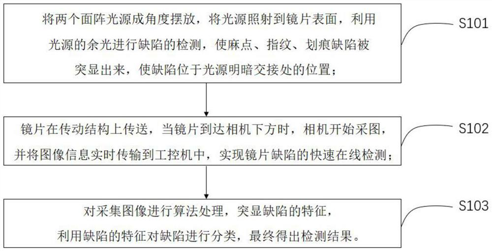
[0008] (1) It is difficult to judge the type and location of defects by scattering energy analysis
[0009] (2) The visual inspection method is easily affected by human subjective factors, such as work experience, fatigue, environment, and responsibility, so that the test results will have large differences, and its stability and reliability are difficult to guarantee; Time-consuming and labor-intensive, and inspectors need relevant training: it is difficult to quantify the parameters such as the geometric size of the detected defects, the accuracy is difficult to guarantee, and accurate calibration cannot be performed, and many other defects
[0010] (3) Although the sensitivity and accuracy of the machine vision imaging method are improved compared with other methods, the surface defects of the lens are very small and difficult to distinguish, and the accuracy requirements are getting higher and higher. Therefore, the detection of lens defects in machine vision is of great importance method needs to be improved
[0011] The difficulty in solving the above technical problems lies in: the surface defects of the lens are very small, it is difficult to distinguish, and the precision requirements are getting higher and higher

Method used


Image

  • Lens surface defect detection method and system based on machine vision, product and terminal
  • Lens surface defect detection method and system based on machine vision, product and terminal
  • Lens surface defect detection method and system based on machine vision, product and terminal

Examples


Embodiment Construction

[0056] In order to make the above objects, features and advantages of the present invention more comprehensible, specific implementations of the present invention will be described in detail below in conjunction with the accompanying drawings. In the following description, numerous specific details are set forth in order to provide a thorough understanding of the present invention. However, the present invention can be implemented in many other ways different from those described here, and those skilled in the art can make similar improvements without departing from the connotation of the present invention, so the present invention is not limited by the specific implementations disclosed below.

[0057] It should be noted that when an element is referred to as being “fixed” to another element, it can be directly on the other element or there can also be an intervening element. When an element is referred to as being "connected to" another element, it can be directly connected ...


PUM


Abstract

The invention discloses a lens surface defect detection method and system based on machine vision, a product and a terminal, and relates to the technical field of digital image processing. Two area array light sources are placed at a certain angle, the light sources irradiate the surface of the lens, residual light of the light sources is used for defect detection, so that the defects such as pocks, fingerprints and scratches are highlighted, and the defects are located at the light and shade junction of the light sources; the lens is conveyed on the transmission structure, and when the lens reaches the position below the camera, the camera starts to acquire images and transmits image information to the industrial personal computer in real time, so that rapid online detection of lens defects is realized; and algorithm processing is performed on the acquired image, the characteristics of the defects are highlighted, the defects are classified by utilizing the characteristics of the defects, and finally a detection result is obtained. The mode that the two area array light sources emit light to the two sides is adopted, residual light of the light sources is used for detecting the defects of the lens, the showing force on the defects on the surface of the lens can be enhanced, and a high-quality defect image is obtained.

Description

technical field [0001] The disclosure of the present invention relates to the technical field of digital image processing, in particular to a machine vision-based lens surface defect detection method, system, product, and terminal. Background technique [0002] Since the mid-1990s, the glasses industry has entered a mature stage from a period of rapid development, and people's requirements for the quality of optical lens surfaces have also been continuously improved. It is inevitable that some defects such as scratches and pitting will occur in the process of lens processing, especially the diffraction or scattering caused by scratches will seriously affect the performance of the optical system. Therefore, many scientific research institutions and scholars at home and abroad have carried out research on the detection of lens surface defects. [0003] With the continuous exploration, research and development of lens surface defect detection methods at home and abroad, many d...

Claims


Application Information

Patent Timeline
Patent Type & Authority Applications(China)
IPC IPC(8): G01N21/01G01N21/95
CPCG01N21/01G01N21/958G01N2021/9583
Inventor 袁帅鹏王思琦闫鹏吉刘洋陈涛王敏雪周学博
Owner 菲特(天津)检测技术有限公司
Why Eureka
Try Eureka