Hardware-in-loop closed-loop test method and system for battery management system

A technology of battery management system and test method, which is applied in the direction of electrical test/monitoring, general control system, control/regulation system, etc. It can solve the problems of low closed-loop test coverage and insufficient closed-loop degree, so as to improve product design and improve efficiency effect

Inactive Publication Date: 2021-08-13
HEFEI GUOXUAN HIGH TECH POWER ENERGY
View PDF8 Cites 3 Cited by
  • Summary
  • Abstract
  • Description
  • Claims
  • Application Information

AI Technical Summary

Problems solved by technology

[0005] In order to solve the problem that the closed-loop test coverage rate of the battery management system is not high due to the insufficient degree of closed-loop test in the closed-loop test of the battery management system, and to optimize the existing battery management system in-loop closed-loop test, the present invention provides a hardware-in-loop test of the battery management system. The closed-loop test method and system, the specific scheme is as follows:

Method used


Image

  • Hardware-in-loop closed-loop test method and system for battery management system
  • Hardware-in-loop closed-loop test method and system for battery management system
  • Hardware-in-loop closed-loop test method and system for battery management system

Examples


Embodiment 1

[0054] Embodiment 1 comprises the following steps:

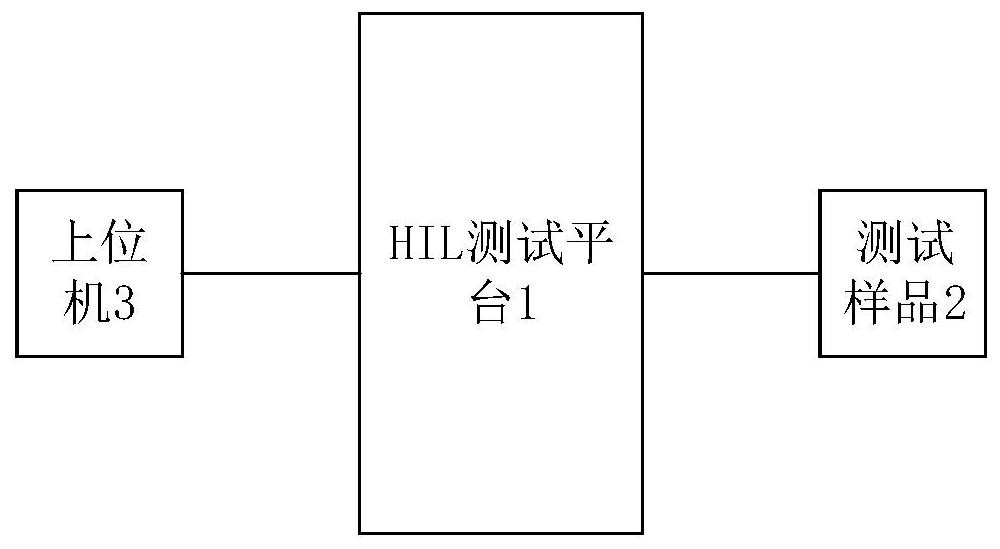
[0055] S1, connect the BMU slave control unit and the HIL test platform 1;

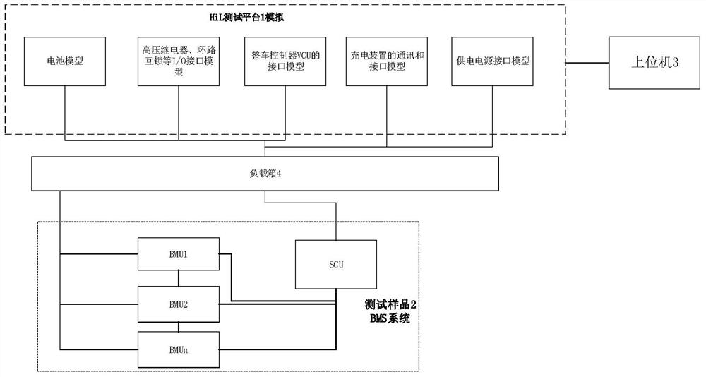
[0056] S2. Use dSPACE's ConfigurationDesk to configure the real-time external hardware interface, which is used to manage the signal path between the BMU slave control unit and the model; set the I / O and monitoring, and the model of the controlled object based on dSPACE;

[0057]S3. Generate codes for the I / O, monitoring, and controlled object models set in step S3, and download them to the HIL test platform 1 through dSPACE's ControlDesk for signal interaction testing, and record experimental data.

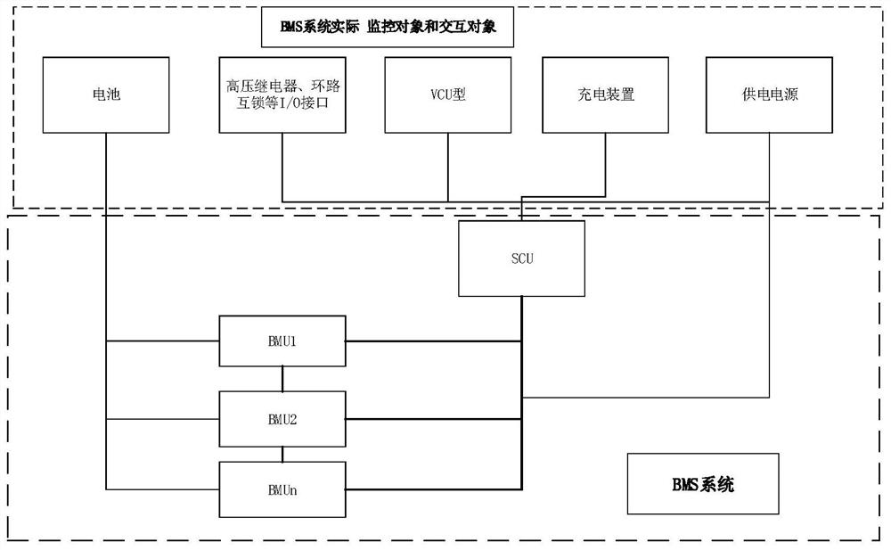
[0058] The model includes: a battery model, including parameter information such as the voltage, temperature, and balanced current of a single or module battery. The battery model adopts a second-order circuit model, and the model is integrated in the HIL test platform 1;

[0059] The interface model between the BMU slave control unit and the SCU: CAN...

Embodiment 2

[0062] Embodiment 2 comprises the following steps:

[0063] S1, connecting the SCU host control unit and the HIL test platform 1;

[0064] S2. Use dSPACE's ConfigurationDesk to configure the real-time external hardware interface, which is used to manage the signal path between the SCU host control unit and the model; set the I / O and monitoring, and the model of the controlled object based on dSPACE;

[0065] S3. Generate codes for the I / O, monitoring, and controlled object models set in step S3, and download them to the HIL test platform 1 through dSPACE's ControlDesk for signal interaction testing, and record experimental data.

[0066] The models include:

[0067] SCU host control unit and high voltage relay, loop interlock I / O interface model, said model is integrated in HIL test platform 1;

[0068] The communication interface model between the SCU host control unit and n BMUs: CAN communication establishes a communication model by importing DBC files; the daisy chain is...

Embodiment 3

[0073] Embodiment 3 comprises the following steps:

[0074] S1, connect the BMS system and the HIL test platform 1;

[0075] S2. Use dSPACE's ConfigurationDesk to configure the real-time external hardware interface to manage the signal path between the BMS system and the model; set the I / O and monitoring, and the model of the controlled object based on dSPACE;

[0076] S3. Generate codes for the I / O, monitoring, and controlled object models set in step S3, and download them to the HIL test platform 1 through dSPACE's ControlDesk for signal interaction testing, and record experimental data.

[0077] The models include:

[0078] The battery model includes parameter information such as the voltage, temperature, and balanced current of a single or module battery. The battery model adopts a second-order circuit model, and the model is integrated in the HIL test platform 1;

[0079] The model includes: a battery model, including parameter information such as the voltage, temperatu...


PUM


Abstract

The invention relates to the field of battery management system testing, in particular to a hardware-in-loop closed-loop test method and system for a battery management system. The hardware-in-loop closed-loop test method for the battery management system comprises the steps of S1, connecting a test sample and an HIL test platform; S2, configuring a real-time external hardware interface by using Configuration Desk of the dSPACE, wherein the real-time external hardware interface is used for managing a signal path between external hardware and the model, and setting I / O and models of monitored and controlled objects based on dSPACE; and S3, generating codes from the I / O and the models of the monitored and controlled objects set in the step S3, downloading the codes to an HIL test platform through the ControlDesk of dSPACE to carry out signal interaction test, and recording experimental data. The method has the beneficial effects that the closed-loop rate of the BMS hardware simulation HIL test can be improved by setting various models of the monitored and controlled objects.

Description

technical field [0001] The invention relates to the field of battery management system testing, in particular to a hardware-in-loop closed-loop testing method and system for a battery management system. Background technique [0002] In the hardware-in-the-loop simulation test HIL of the battery management system BMS, one of the key links is the closed-loop test of the device under test and the test system. To complete the closed-loop test, the BMS under test is placed in a simulated vehicle environment , which can realize the application scenario test of the battery management system BMS, including fault simulation, vehicle operation, charging and other states. [0003] The integrity of the closed-loop test determines the coverage of the HIL test. A high test coverage can solve the functional requirements and potential safety risks of the project as completely as possible during the development phase, and minimize the after-sales costs caused by development problems. value....

Claims


Application Information

Patent Timeline
Patent Type & Authority Applications(China)
IPC IPC(8): G05B23/02G01R31/3842G01R31/396
CPCG05B23/0213G01R31/3842G01R31/396G05B2219/24065
Inventor 杨刘倩王自卫张峥彭文
Owner HEFEI GUOXUAN HIGH TECH POWER ENERGY
Why Eureka
Try Eureka