Designing method for riser of automobile motor end cover and casting mold of riser

A technology of motor end cover and design method, which is applied in computer-aided design, manufacturing tools, casting and molding equipment, etc., can solve the problems of shrinkage porosity, inconvenient operation of riser parts, low processing efficiency, etc., and achieves simple and clear design ideas. The process is simple and efficient, and the effect of mold preparation is convenient

Active Publication Date: 2021-08-13
NINGBO QUANLI MACHINERY MOLD
View PDF4 Cites 0 Cited by
  • Summary
  • Abstract
  • Description
  • Claims
  • Application Information

AI Technical Summary

Problems solved by technology

Gravity casting includes sand casting, metal casting, investment casting, lost foam casting, etc. Among them, the whole process of sand core casting is relatively complicated, resulting in low processing efficiency. It is necessary to use the method of darkening the riser in the middle, but the riser designed according to the traditional casting process design theory does not sufficiently feed the hot joint of the casting, so it is easy to cause shrinkage inside the casting due to insufficient feeding. Pores, shrinkage; or there will be inconvenient operation on the riser, which makes the paint on it always incomplete, affecting the overall appearance of the casting

Method used


Image

  • Designing method for riser of automobile motor end cover and casting mold of riser
  • Designing method for riser of automobile motor end cover and casting mold of riser
  • Designing method for riser of automobile motor end cover and casting mold of riser

Examples


Embodiment 1

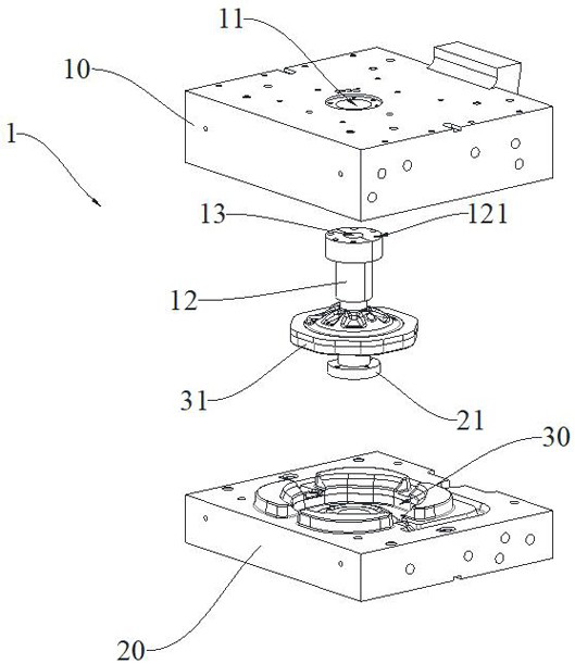
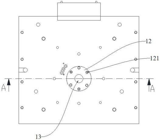
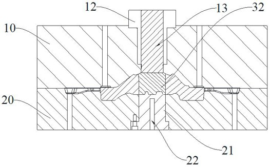
[0060] A riser design method for an automobile motor end cover, comprising the following steps:

[0061] (1) Use UG-3D software to analyze and find out the heat joint, which is located in the middle of the casting;

[0062] (2) The thermal junction is equivalent to a cylindrical structure, and the size of the thermal junction is determined: radius R 1 30mm, height H 1 50mm;

[0063] (3) Calculate the volume V of the thermal junction1 =π×R 1 2 ×H 1 =3.14×30 2 ×50=141300mm 2 , to calculate the mass M of the thermal junction 1 =ρ 1 ×V 1 , where ρ 1 is the density of thermal nodes, V 1 is the volume of thermal junction, where ρ 1 =2700kg / m 3 , namely M 1 =ρ 1 ×π×R 1 2 ×H 1 , Substitute the above data into the formula to get M 1 =0.382kg.

[0064] (4) Introducing M 2 =2M 1 Calculation formula to calculate the mass M of the riser 2 =a×ρ 1 ×π×R 1 2 ×H 1 , that is, M 2 =0.764kg.

[0065] (5) Calculate the volume V of the riser 2 = M 2 / ρ 2 , where ρ 2 ...

Embodiment 2

[0068] A riser design method for the end cover of an automobile motor is the same as that in Embodiment 1, except that the mass of the thermal joint in step (4) is M 1 , the mass of the riser is M 2 , and M 2 =0.5M 1 .

Embodiment 3

[0070] A riser design method for the end cover of an automobile motor is the same as that in Embodiment 1, except that the mass of the thermal joint in step (4) is M 1 , the mass of the riser is M 2 , and M 2 = M 1 .


PUM


Abstract

The invention discloses a designing method for a riser of an automobile motor end cover, which comprises the following steps: S1, analyzing and finding out a hot spot of a casting by applying simulation software, and positioning the hot spot in the middle of the casting; S2, enabling the hot spot to be equivalent to a cylinder structure, and determining the size of the hot spot, wherein the radius is R<1> and the height is H<1>; S3, calculating the mass M<1> of the hot spot according to the formula: M<1> = [rho]<1> * V<1>, wherein [rho]<1> is the density of the hot spot, and V<1> is the volume of the hot spot; S4, calculating the mass M<2> of the riser according to a calculation formula that M<2> is equal to aM<1>; S5, designing the riser into a cylindrical structure, determining the radius R<2> of the riser, and calculating the height H<2> of the riser, wherein R<2> is smaller than R<1>, and R<2> is equal to bR<1>; and S6, calculating the height H<2> of the riser. the size of the dead head is calculated and optimized based on the three-dimensional simulation process, the casting is fed by adopting the dead head with the size, the casting can be fully fed, and the qualified rate of products is increased.

Description

technical field [0001] The present application relates to the technical field of gravity casting, in particular to a method for designing a riser of a gravity casting automobile motor end cover and a casting mold thereof. Background technique [0002] Gravity casting refers to the process in which molten metal is poured into the mold under the action of the gravity of the earth, also known as gravity casting. Gravity casting includes sand casting, metal casting, investment casting, lost foam casting, etc. Among them, the whole process of sand core casting is relatively complicated, resulting in low processing efficiency. It is necessary to use the method of darkening the riser in the middle, but the riser designed according to the traditional casting process design theory does not sufficiently feed the hot joint of the casting, so it is easy to cause shrinkage inside the casting due to insufficient feeding. Pores, shrinkage; or there will be inconvenient operation of the ri...

Claims


Application Information

Patent Timeline
Patent Type & Authority Applications(China)
IPC IPC(8): G06F30/17G06F30/20B22C9/08B22C9/22B22D15/00G06F119/08
CPCB22C9/088B22C9/22B22D15/00G06F30/17G06F30/20G06F2119/08
Inventor 王庆林陈行全贺贤栋
Owner NINGBO QUANLI MACHINERY MOLD
Why Eureka
Try Eureka