Energy router operation control method and system

An operation control and router technology, which is applied in the field of energy router operation control methods and systems, can solve the problems of wide distribution of micro-source output voltages, large differences in output characteristics, increased module overcurrent, short circuit, etc., and achieves high noise immunity. and real-time, avoid unnecessary oscillation, the effect of high-efficiency power range

Active Publication Date: 2022-06-21
HUNAN UNIV
View PDF0 Cites 0 Cited by
  • Summary
  • Abstract
  • Description
  • Claims
  • Application Information

AI Technical Summary

Problems solved by technology

On the one hand, such scenarios lack the support of large power grids, and the energy router system does not have sufficient inertia and damping, and various power quality and stability problems emerge; at the same time, various forms of micro-sources have a wide range of output voltages, The large difference in output characteristics leads to the need for the energy router system to have a wide voltage range access capability and complicate the control method; in addition, various sensitive loads in this type of scenario have extremely high requirements for power supply reliability and anti-interference ability, which requires The dynamic and steady-state performance of the system coordinated control method poses high challenges
On the other hand, the environment in such scenarios is harsh, and the energy router system works in extreme conditions for a long time, which increases the probability of overcurrent, short circuit and other faults in the modules in the system. Such safety problems seriously threaten the stability and reliability of the entire system. Reliability, in order to ensure the rapid recovery and stable operation of the system after a fault occurs, the low-voltage ride-through capability of the energy router is facing more severe challenges

Method used


Image

  • Energy router operation control method and system
  • Energy router operation control method and system
  • Energy router operation control method and system

Examples


Embodiment Construction

[0023] The embodiment of the present invention includes the following steps:

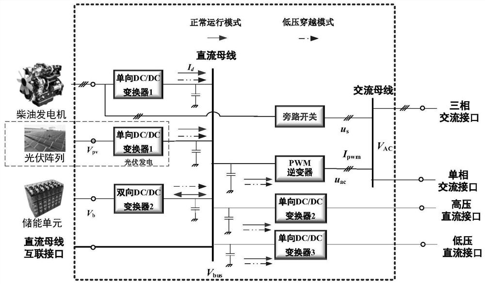
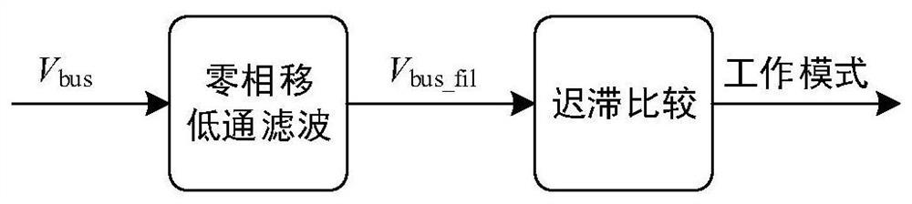
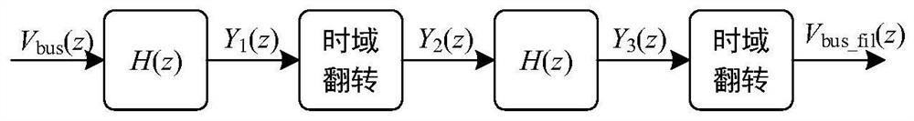
[0024] 1) According to the DC bus voltage V bus To judge the low-voltage fault and determine the working mode of the system, it includes the following steps: ① Sampling the DC bus voltage V bus , the DC bus voltage V bus After filtering by the zero-phase-shift low-pass filter H(z), the signal V is obtained bus_fil , thereby filtering out the DC bus voltage V bus on the noise interference, and to ensure real-time performance. Among them, h(z) is zero-phase-shifted low-pass filter H(z) The internal conventional phase-shifted low-pass filter satisfies H(z)=|h(z)|2 ;DC bus voltage V bus with the filtered signal V bus_fil Satisfy V bus_fil (z)=H(z)V bus (z);

[0025] ②For the filtered signal V bus_fil A hysteresis comparison is performed to determine whether the current system is in normal operating mode or low-voltage ride-through mode, while avoiding frequent switching between operating modes....


PUM


Abstract

The invention discloses an energy router operation control method and system, which divides the energy router into two working modes: a normal operation mode and a low-voltage ride-through mode. In the normal operation mode, the coordination and stability of the system is achieved by scheduling the output of the diesel generator in stages, maintaining the power balance between the source and the load, and at the same time realizing the SOC regulation of the energy storage unit to ensure the efficient operation of the energy router; The generator and photovoltaic power generation unit output according to the maximum output power, the energy storage unit adopts constant voltage control, and the system-level coordinated control is used to suppress the continuous drop of the bus voltage, support the rapid recovery of the bus voltage, and ensure the effective ride-through of low-voltage faults of the energy router. At the same time, the zero-phase-shift low-pass filter and hysteresis comparison method are used for low-voltage drop detection to ensure real-time detection and anti-interference performance, and to avoid frequent switching between modes.

Description

technical field [0001] The invention relates to the technical field of micro-source interconnection power supply and control, in particular to an energy router operation control method and system. Background technique [0002] Energy router refers to a power electronic device that integrates information flow and energy flow to realize multi-source interconnection. Energy router topology interfaces such as figure 1 As shown, it includes two DC busbars: the diesel generator is connected to the DC busbar via a one-way AC / DC converter, the photovoltaic array is connected to the DC busbar via a one-way DC / DC converter 1, and the energy storage unit is connected via a two-way DC / DC converter. DC bus, DC bus through one-way DC / DC converters 2 and 3 respectively form high-voltage and low-voltage DC interfaces to supply power. At the same time, the DC bus has a DC bus interconnection interface to facilitate the interconnection of external systems; the diesel generator is connected t...

Claims


Application Information

Patent Timeline
Patent Type & Authority Patents(China)
IPC IPC(8): H02J3/00H02J3/46H02J3/28H02J3/02
CPCH02J3/002H02J3/466H02J3/28H02J3/02H02J2300/26Y02E70/30
Inventor 周乐明周杰易伟浪刘琦王舒克刘思怡肖志强
Owner HUNAN UNIV
Why Eureka
Try Eureka