Joining method for a medical device

A joint method, a technology of medical technology, applied in the direction of surgery, application, medical science, etc., can solve the problems of pollution and corrosion of the connection position, complicated manufacturing method, increased cost, etc.

Pending Publication Date: 2021-08-13
AESCULAP AG
View PDF0 Cites 0 Cited by
  • Summary
  • Abstract
  • Description
  • Claims
  • Application Information

AI Technical Summary

Problems solved by technology

This disadvantageously leads to contamination and corrosion of the connection locations
In order to avoid this, the connection points are

Method used


Image

  • Joining method for a medical device
  • Joining method for a medical device
  • Joining method for a medical device

Examples


Embodiment Construction

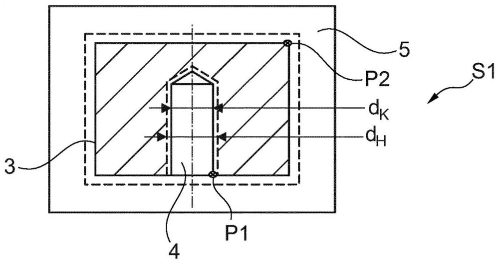
[0028] FIG. 1 shows an embodiment of the joining method according to the invention for a medical technology device 1 which, for the sake of illustration, is represented here as having a shaft or handle 2 and a simple, A cylindrical or cuboidal adapter or working head 3 , for example in the form of a surgical hammer, is shown as a surgical instrument. Depending on the application, however, any different shape of the working head 3 can be selected.

[0029] Figure 1A The heating step S1 is shown. A working head 3 with an opening 4, in this example a hole or a blind hole, is arranged on an induction heating device 5 and heated by induction heating. At the same time, preferably at a point P1 close to the edge of the opening and / or at a point P2 of the adapter at a distance therefrom, the temperature of the adapter or the working head 3 is measured (according to the specific case a temporal sum and / or local (axial) temperature distribution). As an alternative or in addition, op...


PUM


Abstract

Joining method for a medical device (1), in particular a surgical instrument or implant, with a shaft (2) and an attachment (3) to be secured on the latter, said method having the following steps: heating (S1) the attachment (3) or cooling the shaft (2), such that an internal diameter (dH) of an opening (4) of the heated attachment (3) is greater than an external diameter (D) of the shaft (2), then placing (S2) the shaft (2) into the opening (4) of the attachment (3), and then cooling (S3) the attachment (3), so as to shrink the latter onto the shaft (2) in a manner substantially free of gaps, or heating the shaft (2), such that the shaft (2) and the opening (4) are connected by an interference fit. The present invention further relates to a corresponding medical device (1) and to a use of the joining method for producing such a medical device.

Description

technical field [0001] Medical technology devices must meet high demands in terms of functional reliability, tolerances and especially sterility / maintenance of sterility. This applies in particular to connection points of such devices at which two components are firmly connected to each other. The following concerns, for example, the connection position of a surgical instrument with a handle and a working head, for example a surgical hammer. It should be noted, however, that the same problem applies to many other medical technology devices and to the different connection points of these devices. Background technique [0002] According to the prior art, the handle is joined to the working head (actuator) by press-fitting the components together, for example manually, and preventing axial and radial slippage by means of a cross pin or a stop pin. At the same time, the cross pin is pressed into a hole extending through the handle and the working head and must then be fitted b...

Claims


Application Information

Patent Timeline
IPC IPC(8): A61B17/88
CPCA61B2017/00526A61B17/88A61B17/92A61B2090/0813A61B17/56A61B2017/00477A61B2017/00836B23P11/025
Inventor 贾尼娜·阿克曼斯文·巴泰勒墨斯简·达曼安德烈亚斯·德亨多夫缇欧·马特斯埃尔克·普利
Owner AESCULAP AG
Why Eureka
Try Eureka