
Spray head for fire fighting

A sprinkler head and fire-fighting technology, which is applied in fire rescue and other directions, can solve problems such as water leakage, joint leakage, unfavorable fire point extinguishing work, etc., so as to avoid overall disassembly and enhance resistance

Inactive Publication Date: 2021-08-17
温谟宇
View PDF0 Cites 0 Cited by
  • Summary
  • Abstract
  • Description
  • Claims
  • Application Information

AI Technical Summary

Problems solved by technology

[0004] However, in the actual use process, because the glass body explodes, the water block will be pushed out at the same time, so when the glass body is broken under the action of external force, it is necessary to close the water valve main gate to cut off the water pipe. In the process of shutting it down and maintaining it, the entire fire-fighting device is in a non-working state, so that it cannot be remedied at the first time when a fire occurs during the maintenance process. During the process, it needs to be taken out through the screw thread, so as to install a new sprinkler head for replacement. Therefore, in the actual use process, the sprinkler head after the threaded connection is rusted, so it is not easy to take it out. At the same time, After the installation thread on the water pipe is damaged, water leakage will occur at the joint when installing a new sprinkler head, so that the sprinkler head is not only prone to water leakage during the replacement process, but at the same time, the replaced sprinkler head will not reappear. utilization, resulting in waste of equipment
[0005] At the same time, the existing splash plate is fixed to the bottom of the shower head, so that after the water flow hits the splash plate, the area covered by it is relatively fixed, so that the fire extinguishing area of ​​the spray nozzle is relatively Therefore, it is not conducive to the extinguishing of fire points in a wide range

Method used


Image

  • Spray head for fire fighting
  • Spray head for fire fighting
  • Spray head for fire fighting

Examples


Embodiment Construction

[0025] The following will clearly and completely describe the technical solutions in the embodiments of the present invention with reference to the accompanying drawings in the embodiments of the present invention. Obviously, the described embodiments are only some, not all, embodiments of the present invention. Based on the embodiments of the present invention, all other embodiments obtained by persons of ordinary skill in the art without making creative efforts belong to the protection scope of the present invention.

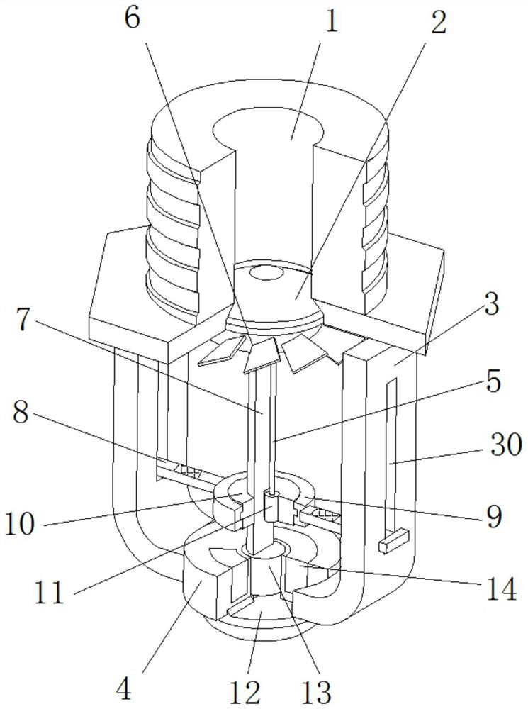
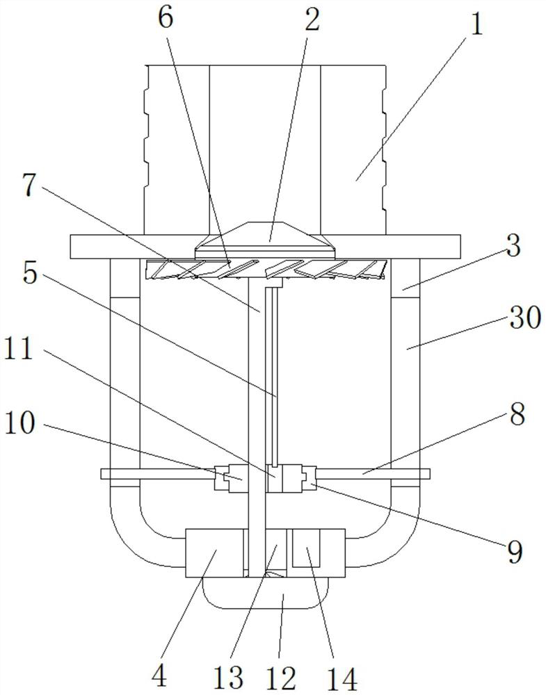
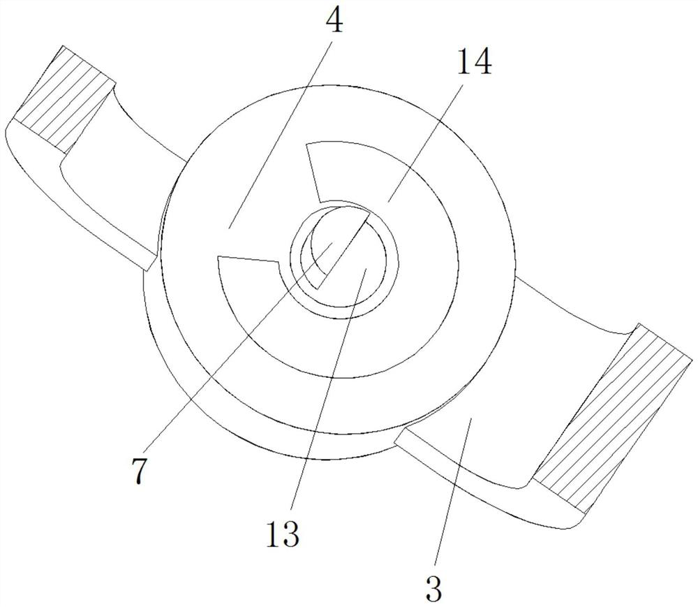
[0026] see Figure 1-5 , a sprinkler head for fire extinguishing, comprising an installation block 1, the inner wall of the installation block 1 is provided with a water outlet, and the bottom of the installation block 1 is movably installed with a blocking block 2 for blocking the water outlet, and the installation block 1 Both sides of the bottom are fixedly equipped with support arms 3 respectively, and the bottom end of the support arms 3 is fixedly equipp...


PUM


Abstract

The invention relates to the technical field related to fire fighting equipment, and discloses a spray head for fire fighting. The spray head comprises a mounting block, wherein a water outlet channel is formed in the inner wall of the mounting block, a plugging block used for plugging the water outlet channel is movably arranged at the bottom of the mounting block, and supporting arms are fixedly arranged on the two sides of the bottom of the mounting block respectively. According to the spray head, a fixed magnetic block is arranged on a fixing seat, meanwhile, a cutting block is attracted by the fixed magnetic block, the cutting block supports the plugging block through a driving shaft and a detection rod, so that after the detection rod is broken, the cutting block is manually pushed to realize that the plugging block plugs the water outlet channel of the mounting block, and the purpose of plugging at any time is achieved; and moreover, through the interaction between the adsorption force between the cutting block and the fixed magnetic block and the water flow, a water dispersing disc can move up and down in a reciprocating mode, change of the water dispersing area of the water dispersing disc is realized, and finally the purposes of real-time plugging without cutting off a main switch and changing the water dispersing area are achieved.

Description

technical field [0001] The invention relates to the related technical field of fire-fighting equipment, in particular to a sprinkler head for fire-fighting and extinguishing. Background technique [0002] The fire sprinkler is used in the fire sprinkler system. When a fire breaks out, the water is sprayed out through the sprinkler splash plate to extinguish the fire. It is divided into a pendant sprinkler, a vertical sprinkler, a common sprinkler, and a side wall sprinkler Nozzle etc. [0003] The working principle of the existing drooping fire extinguishing nozzle is: when a fire occurs, the glass body expands due to the increase in temperature, and then the water blocking block is washed out by the impact of water, and then the sprayed water acts on the splash plate Finally, the fire extinguishing work is realized through the sprayed water flow. [0004] However, in the actual use process, because the glass body explodes, the water block will be pushed out at the same ti...

Claims


Application Information

Patent Timeline
IPC IPC(8): A62C31/02A62C31/28
CPCA62C31/02A62C31/28
Inventor 温谟宇
Owner 温谟宇
Learn More