
Automatic die punching machine for lithium battery shell

An automatic punching and lithium battery technology, which is applied in product die cutting and industrial production, can solve problems such as low work efficiency, raw material transportation, and positioning difficulties, and achieve the effects of smooth surface, difficult transportation and positioning, and high efficiency

Inactive Publication Date: 2021-08-17
深圳联钜自控科技有限公司
View PDF0 Cites 1 Cited by
  • Summary
  • Abstract
  • Description
  • Claims
  • Application Information

AI Technical Summary

Problems solved by technology

[0002] In the existing industrial production process, the punching process is generally to cut the raw material into a suitable size and then stamp it through the punching machine. If the workpiece that needs to be punched is small, it is difficult to transport and position the raw material after cutting, and The efficiency of punching each piece of raw material one by one is also relatively low; the invention discloses an automatic punching machine for a lithium battery case. When punching a workpiece with a relatively small volume, the raw material is punched and then passed through a fixed-width cutting machine and a fixed-length cutting machine. The cutting machine cuts the workpiece into a suitable size after punching the die; compared with the prior art of cutting first and then punching the die, the present invention punches the die first and then cuts, which can not only solve the problem of difficult transportation and positioning after cutting first, but also improve Improve the working efficiency of the die

Method used


Image

  • Automatic die punching machine for lithium battery shell
  • Automatic die punching machine for lithium battery shell
  • Automatic die punching machine for lithium battery shell

Examples


Embodiment 1

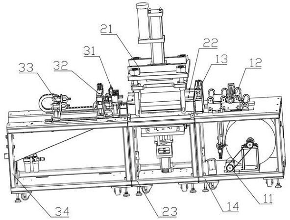
[0029] Embodiment 1: as figure 1 As shown, an automatic punching machine for a lithium battery shell is provided with a feeding mechanism, a die mechanism and a cutting and blanking mechanism, and the feeding mechanism is provided with a feeding motor assembly 11, a tension assembly 12, a pressing cylinder assembly 13 and a feeding frame 14. The die mechanism is provided with a die machine 21, a guide plate assembly and a die frame 24; the slitting and blanking mechanism is provided with a longitudinal slitting assembly 31, a transverse slitting assembly 32, a pulling assembly 33 and a blanking machine Rack 34.

[0030] The raw material is conveyed to the tension assembly 12 through the feeding motor assembly 11, and the tension assembly 12 stretches the raw material and then conveys it to the pressing cylinder assembly 13; the raw material enters the first guide plate 21 after passing through the pressing cylinder assembly 13; the raw material passes through the first guide p...

Embodiment 2

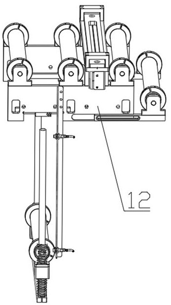
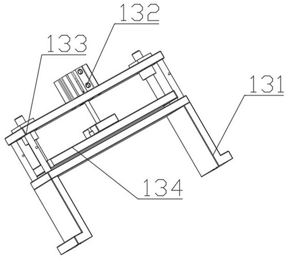
[0031] Embodiment 2: as figure 2 As shown, in order to ensure that the surface of the raw material entering the die machine 22 is smooth and wrinkle-free, a binder cylinder assembly 13 is provided. The binder cylinder assembly is provided with a support seat 131, a binder cylinder 132, a binder cylinder frame 133 and a binder plate 134; the support seat 131 is installed on the feeding frame 14, the pressing cylinder frame 133 is installed on the support seat 131; the pressing cylinder 132 is installed on the pressing cylinder frame 133; The pressing plate 134 is connected to the pressing cylinder 132, and the pressing plate 134 is located above the support seat 131; when the raw material enters the pressing cylinder assembly 13 from the tension assembly 12, the raw material passes through the supporting seat 131 and the press. Pass between the material plates 134; according to the thickness of the raw material, the pressing cylinder drives the pressing plate to move, and the ...

Embodiment 3

[0032] Embodiment 3: as image 3 As shown, in order to prevent the deviation of the raw material and the material after the die during the conveying process, a guide plate assembly is provided. The guide plate assembly is provided with a first guide plate and a second guide plate. The first guide plate There are supporting legs 221, flat plates 222, sliding blocks 223 and wing nuts 224; the supporting legs 221 are installed on the left and right sides of the fixed plate, and the flat plates 222 are installed on the supporting legs; An adjustment thread hole is provided, and a chute is provided on the sliding block 223, and the wing nut 224 passes through the adjustment thread hole and the chute to fix the sliding block 223 on the flat plate 222; The structure of the first guide plate is consistent with that of the second guide plate; the distance between the two slide blocks can be fine-tuned through the chute on the slide block, and the position of the adjustment thread hole ...


PUM


Abstract

The invention discloses an automatic die punching machine for a lithium battery shell. The machine comprises a feeding mechanism, a die punching mechanism and a slitting and discharging mechanism, wherein the die punching mechanism is located between the feeding mechanism and the slitting and discharging mechanism; the feeding mechanism is provided with a feeding motor assembly, a tension assembly, a pressing air cylinder assembly and a feeding rack; the feeding motor assembly, the tension assembly and the pressing air cylinder assembly are installed on the feeding rack; the die punching mechanism is provided with a die punching machine, a guide plate assembly and a die punching machine frame; the die punching machine and the guide plate assembly are installed on the die punching machine frame; the slitting and discharging mechanism is provided with a longitudinal slitting assembly, a transverse slitting assembly, a material pulling assembly and a discharging rack; and the discharging rack is provided with a guide rail and a discharging groove, the longitudinal slitting assembly, the transverse slitting assembly and the material pulling assembly are installed on the guide rail. The automatic die punching machine can achieve automatic punching and cutting operation, is easy to operate and high in operation efficiency, and has good market application value.

Description

technical field [0001] The invention relates to the field of industrial production, in particular to the field of product die cutting. Background technique [0002] In the existing industrial production process, the stamping process is generally to cut the raw material into a suitable size and then stamp it through the stamping machine. If the workpiece that needs to be stamped is small, it is difficult to transport and position the raw material after cutting, and The working efficiency of stamping each piece of raw material one by one is also relatively low; the invention discloses an automatic punching machine for a lithium battery case. The cutting machine cuts the workpiece after punching to a suitable size; compared with the prior art of cutting first and then punching, the present invention punches the die first and then cuts, which not only solves the problem of difficult transportation and positioning after cutting, but also improves Improve the working efficiency o...

Claims


Application Information

Patent Timeline
Patent Type & Authority Applications(China)
IPC IPC(8): B21D22/02B21D37/10B21D43/28B21D43/08B21D45/04
CPCB21D22/02B21D37/10B21D43/08B21D43/28B21D45/04
Inventor 刘田凤
Owner 深圳联钜自控科技有限公司
Learn More