Pressing device
A compression device and compression piece technology, applied in the direction of connecting components, pins, mechanical equipment, etc., can solve problems such as extension looseness, dead spots, and inability to tighten
- Summary
- Abstract
- Description
- Claims
- Application Information
AI Technical Summary
Problems solved by technology
Method used
Image
Examples
Embodiment 1
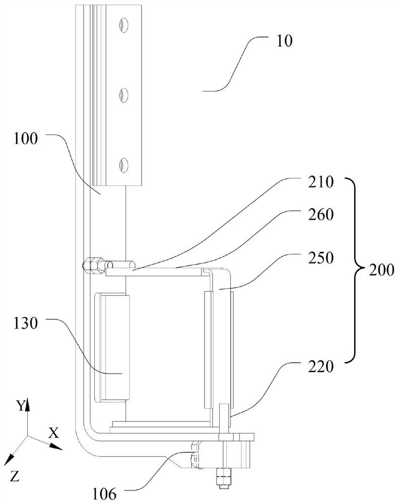
[0041] like figure 1 As shown, this embodiment provides a pressing device 10 for pressing an object to be pressed. The pressing device 10 includes: a bracket 100 and a pressing member 200, wherein the bracket 100 is suitable for placing the object to be pressed; The pressing member 200 is provided with a first end 210 along the first direction X, and the pressing member 200 is provided with a second end 220 along the second direction Y; the first end 210 and the second end 220 are respectively connected with the bracket 100 to connect the The object to be pressed is defined between the bracket 100 and the pressing member 200 , and the pressing member 200 is made to press the object to be pressed in the first direction X and the second direction Y.
[0042] In this embodiment, the first direction X and the second direction Y are respectively directions in a three-dimensional space. For example, the first direction X may be a horizontal direction, and the second direction may be...
Embodiment 2
[0045] like figure 1 and figure 2 As shown, this embodiment provides a pressing device 10 . In addition to the technical features of the above embodiments, this embodiment also includes the following technical features.
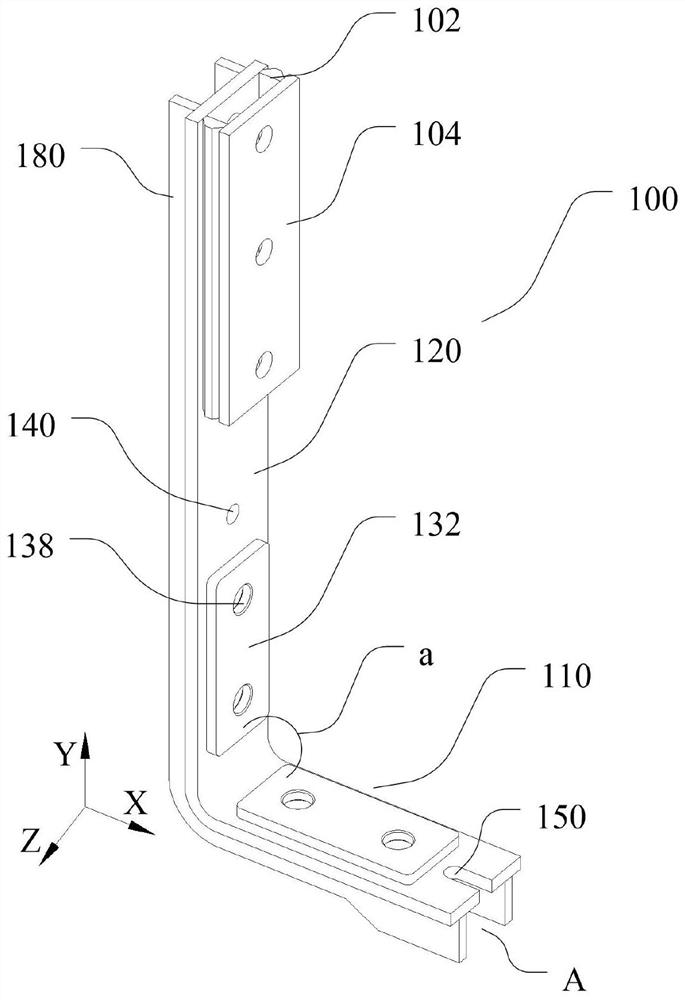
[0046] The bracket 100 includes: a bearing part 110 and a fixing part 120, wherein the bearing part 110 is arranged along the first direction X and is suitable for placing the object to be pressed; the fixing part 120 is arranged along the second direction Y and is suitable for fixing the bracket 100; There is an included angle a between the part 120 and the bearing part 110, the first end 210 is connected with the fixing part 120, and the second end 220 is connected with the bearing part 110, so that the object to be pressed is limited to the bearing part 110, the fixing part 120 and the pressing part 110. between 200 pieces.
[0047] After the pressing device 10 presses the object to be pressed, in some cases, the pressing device 10 needs to be fixed. I...
Embodiment 3
[0049] like figure 1 As shown, this embodiment provides a pressing device 10 . In addition to the technical features of the above embodiments, this embodiment also includes the following technical features.
[0050] The bracket 100 further includes: a first elastic part 130, which is suitable for abutting with the object to be pressed; wherein, the two first elastic parts 130 are respectively disposed on the side of the fixing part 120 facing the object to be pressed and the bearing part 110 faces the side of the object to be pressed.
[0051] The at least two first elastic parts 130 are respectively arranged on the fixing part 120 and the bearing part 110. Due to its elastic function, the first elastic parts 130 can provide pressure for the object to be pressed in the first direction X and the second direction Y respectively. Tight space, and can protect the object to be pressed.
PUM
 Abstract
Description
Claims
Application Information
 - R&D
- Intellectual Property
- Life Sciences
- Materials
- Tech Scout
- Unparalleled Data Quality
- Higher Quality Content
- 60% Fewer Hallucinations
Browse by: Latest US Patents, China's latest patents, Technical Efficacy Thesaurus, Application Domain, Technology Topic, Popular Technical Reports.
© 2025 PatSnap. All rights reserved.Legal|Privacy policy|Modern Slavery Act Transparency Statement|Sitemap|About US| Contact US: help@patsnap.com


