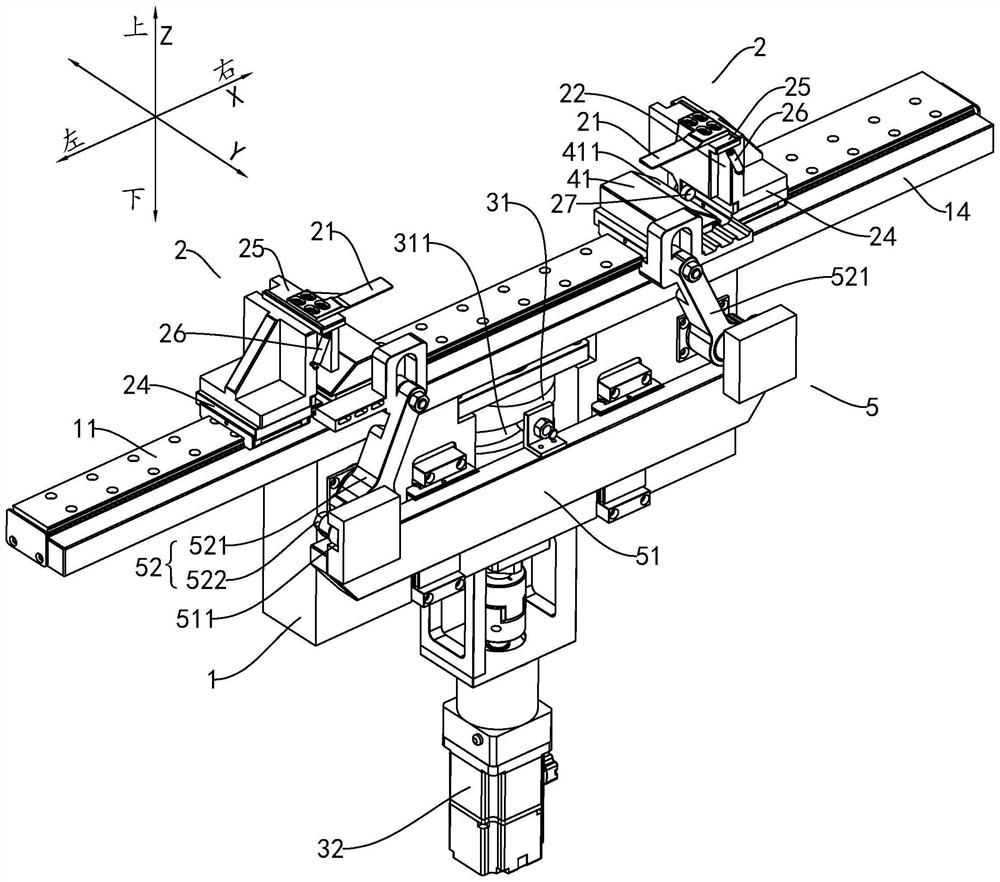
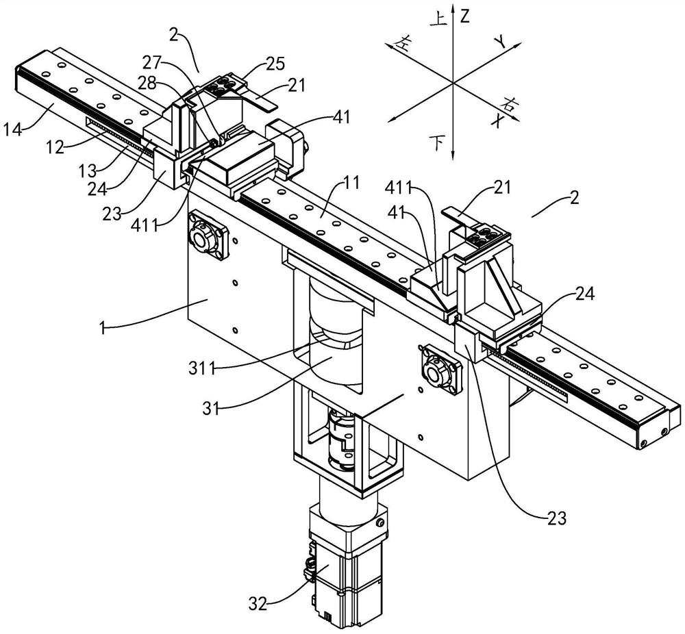
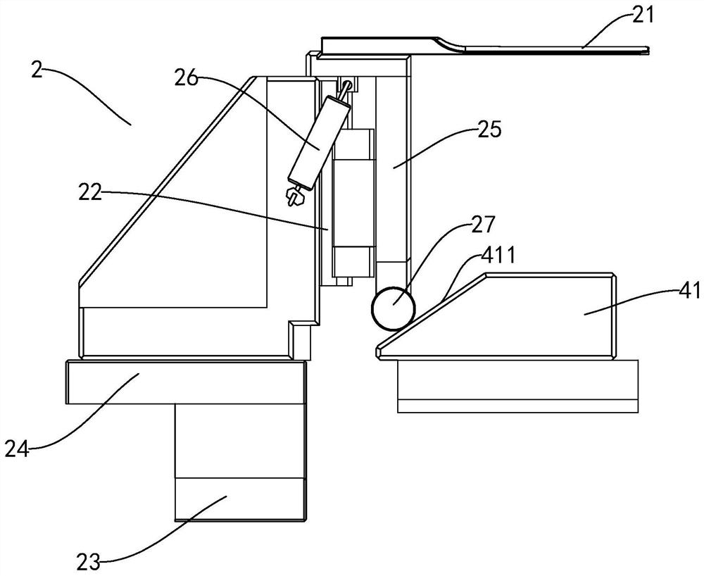
A knife press device and lamination equipment

A knife device and lamination technology, which is applied to equipment for manufacturing primary batteries, primary batteries, and battery assembling machines, etc., can solve the problems of low lamination efficiency, large space occupation, and complicated control, and achieve high lamination efficiency and occupancy. The effect of small space, simplified equipment structure and power control

Active Publication Date: 2022-07-01
GUANGDONG LYRIC ROBOT INTELLIGENT AUTOMATION CO LTD
View PDF12 Cites 0 Cited by
  • Summary
  • Abstract
  • Description
  • Claims
  • Application Information

AI Technical Summary

Problems solved by technology

However, in the prior art, the horizontal and vertical transfer processes of the stacking equipment need to be controlled separately for cell stacking, which has the following disadvantages: (1) Multiple power controls take a long time, and it is necessary to wait for one action to be completed before proceeding to the next one. Action, lamination efficiency is low; (2) Multiple powers need to be used in conjunction with each other, and the control is complicated; (3) It takes up a lot of space and is easy to interfere with other stations

Method used


Image

  • A knife press device and lamination equipment
  • A knife press device and lamination equipment
  • A knife press device and lamination equipment

Examples


Embodiment Construction

[0030] This part will describe the specific embodiments of the present invention in detail, and the preferred embodiments of the present invention are shown in the accompanying drawings. Each technical feature and overall technical solution of the invention should not be construed as limiting the protection scope of the invention.

[0031] In the present invention, if there is a description of a direction (up, down, left, right, front and rear), it is only for the convenience of describing the technical solution of the present invention, rather than indicating or implying that the technical features referred to must have specific characteristics Orientation, construction and operation in a particular orientation, and therefore should not be construed as limiting the invention.

[0032] In the present invention, "several" means one or more, "multiple" means two or more, "greater than", "less than", "exceeding", etc. are understood as not including this number; "above", "below" ...


PUM


Abstract

The invention discloses a knife pressing device and lamination equipment. A rotary member is provided with a track groove, and a transmission component is matched with the track groove. The driving part is used to drive the rotating part to rotate. When the rotating part rotates, the transmission assembly can drive the pushing part to move in the X direction, so as to drive the pressing knife to move in the X direction, and make the inclined surface guide the pressing knife to move in the Z direction. The lamination equipment includes two side-by-side press knife devices and a lamination platform installed between the two knife press devices. The knife pressing device and the lamination equipment of the technical solution realize the simplification of the equipment structure and power control, and realize the movement of the pressing knife in the X direction and the Z direction through a single power, with high lamination efficiency and small space occupation.

Description

technical field [0001] The invention is used in the technical field of laminated battery manufacturing, and in particular relates to a knife pressing device and lamination equipment. Background technique [0002] The laminated battery module is to separate the positive and negative electrode sheets of specified width and length with a separator, and continuously stack them according to the structure of positive electrode sheet / separator / negative electrode sheet. When working, the pressure knife on the pressure knife device needs to be opened and raised in the left and right directions. After the corresponding positive electrode / diaphragm / negative electrode laminated structure is placed, the pressure knife is closed and lowered again to return to the initial position, and so on. until the lamination work is completed. During the lamination process, the way the equipment automatically picks and places the positive and negative plates determines the overall efficiency of the l...

Claims


Application Information

Patent Timeline
Patent Type & Authority Patents(China)
IPC IPC(8): H01M6/00H01M6/14H01M10/04H01M10/0585H01M10/052
CPCH01M6/005H01M6/14H01M10/0404H01M10/0468H01M10/0585H01M10/052Y02E60/10
Inventor 黄宗荣丁媛梁亨健杜义贤
Owner GUANGDONG LYRIC ROBOT INTELLIGENT AUTOMATION CO LTD
Why Eureka
Try Eureka