Rotary stacking equipment and stacking method

A technology of lamination and equipment, applied in the field of rotating lamination equipment and lamination, can solve the problems of speed-up space restriction, slow lamination speed, etc., and achieve the effect of improving lamination efficiency

Active Publication Date: 2018-11-27
SHENZHEN GREENSUN TECH CO LTD
View PDF6 Cites 8 Cited by
  • Summary
  • Abstract
  • Description
  • Claims
  • Application Information

AI Technical Summary

Problems solved by technology

[0003] Z-shaped lamination equipment and swing lamination equipment can only stack one piece at a time, and the lamination speed is relatively slow, which restricts the space for speed-up.

Method used


Image

  • Rotary stacking equipment and stacking method
  • Rotary stacking equipment and stacking method
  • Rotary stacking equipment and stacking method

Examples


Embodiment 1

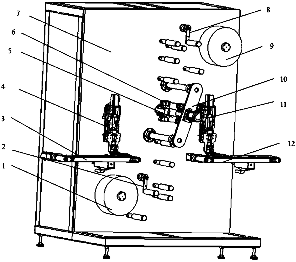
[0033] In one embodiment of the present invention, as Figure 1-3 As shown, a rotary lamination equipment is provided, and the equipment includes: a substrate 7; a first diaphragm unwinding and deviation correction mechanism 1, a first tension control mechanism 2, a negative pole piece conveyor belt 3, a negative pole lamination manipulator 4, a rotating lamination Sheet stage 5, lamination clamping mechanism 6; second diaphragm unwinding and deviation correction mechanism 9, second tension control mechanism 8, positive electrode sheet conveyor belt 12, positive electrode lamination manipulator 11, and support 10 in front of the lamination stage.

[0034] The first diaphragm unwinding and deviation correcting mechanism 1 and the second diaphragm unwinding and deviation correcting mechanism 9 place the diaphragm roll at the same time, and correct the position of the diaphragm to ensure that the position of the diaphragm relative to the substrate is constant. The reason why the ...

Embodiment 2

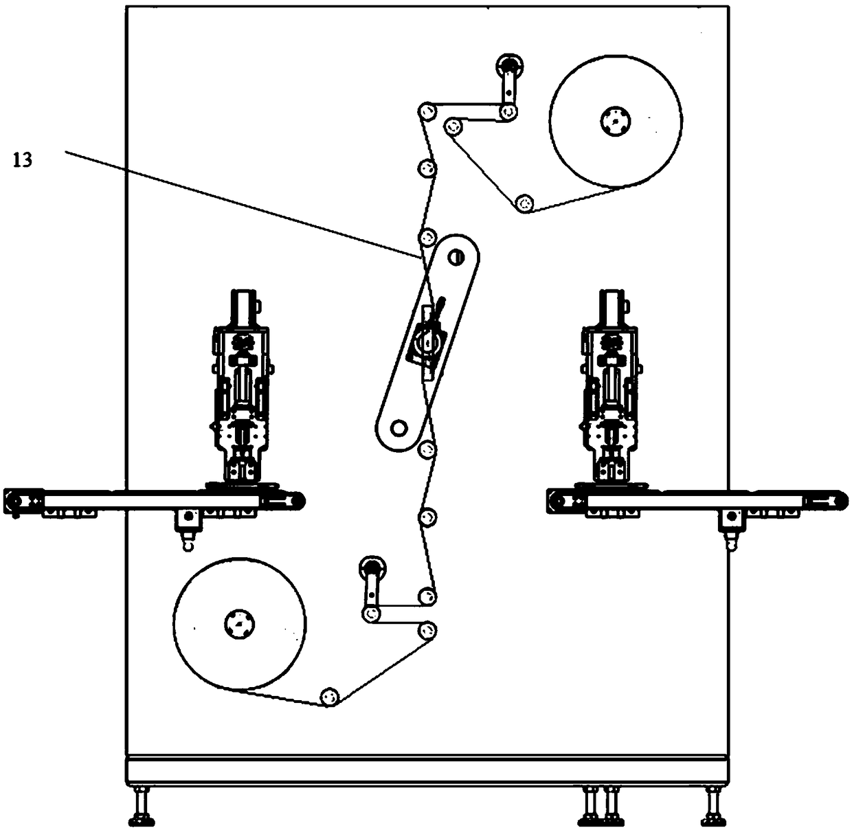
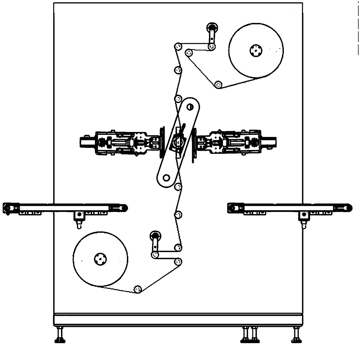
[0039] In an alternative embodiment, such as figure 2 , 3 As shown, the first diaphragm unwinding and correcting mechanism 1 and the second diaphragm unwinding and correcting mechanism 9 place the first diaphragm roll and the second diaphragm roll respectively, and the two diaphragm rolls are joined together to form the diaphragm 13 in working condition.

[0040] Such as Figure 4-9 As shown, the rotating lamination table performs a series of reciprocating lamination movements to realize the lamination action. Such as Figure 4 As shown, the pole piece conveyor belt 3 is used to transport the negative pole piece to the bottom of the negative pole stack manipulator 4; the positive pole piece conveyor belt 12 is used to transport the positive pole piece to the bottom of the positive pole stack manipulator 11; the negative pole stack manipulator 4 sucks The negative electrode sheet is transferred to the rotating lamination table 5; the positive electrode sheet is picked up by...

Embodiment 3

[0049] In an optional embodiment, the negative stack manipulator 4 sucks the negative pole piece and transfers the negative pole piece to the rotating stacking table 5; the positive pole stacking manipulator 11 picks up the positive pole piece and transfers the positive pole piece to the rotating stacking table 5 . The positive / negative lamination manipulator retracts after picking up the sheet on the belt, then rotates to the lamination position, then stretches forward, stacks the pole piece to the lamination table; then shrinks backward, rotates to the lamination position, stretches out to take the sheet.

[0050] Such as Figure 10 As shown, both positive and negative stacked manipulators have a telescopic function and are driven by a servo motor drive 1001 . And the retractable mechanism formed by the servo motor 1001, the ball screw 1002 and the slide rail 1003.

[0051] Specifically, such as Figure 10 As shown, the positive / negative stack manipulator has an inverted ...


PUM


Abstract

The invention relates to rotary stacking equipment and a stacking method. The equipment comprises a substrate, a first membrane unreeling and correcting mechanism, a second membrane unreeling and correcting mechanism, a first tension control mechanism, a second tension control mechanism, a cathode polar plate conveying belt, an anode polar plate conveying belt, a cathode stacking manipulator, an anode stacking manipulator, a rotary stacking table, a stacking table front support, a stacking clip mechanism, a membrane, a cathode plate and an anode plate, wherein the two sets of membrane unreeling correction mechanisms are used for unreeling the membrane at the same time; the two sets of tension control mechanisms are used for controlling the tension force of membrane movement; the two sets of conveying belts are used for conveying the cathode polar plate and the anode polar plate to below the stacking manipulators respectively; the two sets of stacking manipulators are used for respectively drawing the anode polar plate and the cathode polar plate and transferring the polar plates to the stacking table; the stacking clip mechanism is used for fastening the polar plates on the rotarystacking table; and the rotary stacking table rotates by 180 degrees when finishing each time of stacking.

Description

technical field [0001] The invention belongs to the technical field of battery processing, and in particular relates to a rotating stacking device and a stacking method. Background technique [0002] During the battery manufacturing process, the positive and negative electrodes of the battery and the separator need to be laminated. The traditional lamination methods include Z-shaped lamination, bag lamination, swing lamination and composite lamination. Among them, the Z-shaped lamination is a lamination method in which the positive and negative electrodes are repeatedly laminated alternately, and the separator is separated from the middle to form a battery cell. The bag-making lamination is generally to align the upper and lower sides of the positive electrode sheet with the separator, heat press all around to make the positive electrode sheet bag, and then repeatedly alternately laminate with the negative electrode. Composite lamination is a battery cell made by hot-pressi...

Claims


Application Information

Patent Timeline
Patent Type & Authority Applications(China)
IPC IPC(8): H01M10/04H01M6/00
CPCH01M6/005H01M10/0404Y02P70/50Y02E60/10
Inventor 鲁树立宋南海吴鑫樊海彪
Owner SHENZHEN GREENSUN TECH CO LTD
Why Eureka
Try Eureka