
Cooker

A technology for cooking equipment and cooking chambers, which is applied in lighting and heating equipment, household stoves/stoves, heating methods, etc., and can solve difficult control of substrate space, difficulty in accurate door opening action, shelf insertion and removal, inconvenient insertion and removal. Take out the shelf and other issues to achieve the effect of improving safety and ease of use, improving convenience and stability, and reducing the risk of tipping over

Pending Publication Date: 2021-08-17
LG ELECTRONICS INC
View PDF8 Cites 0 Cited by
  • Summary
  • Abstract
  • Description
  • Claims
  • Application Information

AI Technical Summary

Problems solved by technology

[0016] First, when the door is opened, the door can only protrude to the front of the mini-oven to the extent equivalent to the height of the door, thus, when the mini-oven is installed in a small space, it is difficult to accurately perform the opening action of the door and Problems with shelf insertion and removal
[0017] Second, when the door is opened, as the door protrudes to the front of the mini oven to a degree equivalent to the height of the door, there will be a problem that the center of gravity of the mini oven is biased forward
Namely, even with a shelf of thick and heavy material to improve cooking performance, it is difficult to adopt such a shelf due to the risk of the mini oven tipping over
[0021] Thirdly, the access for inserting and removing the shelves and for checking the cooking status is limited to the front of the mini oven, so various restrictions arise
[0022] That is, the direction of inserting and taking out the shelf is only limited to the front-to-back direction, so when the mini oven is installed at a lower position, it is inconvenient to insert and take out the shelf
In addition, the access to check the cooking status is limited to the glass window set on the door, so it is very inconvenient to check the cooking status when the mini oven is set at a lower position
[0023] Often, in order to accurately check the overall cooking status of the food, it is not enough to just open the door, the tray must be removed to do this
[0024] That is, when the user wants to accurately check the overall cooking state of the food, the user must directly take out the shelf after directly opening the door, and then insert the shelf, however, when the mini oven is installed at a lower position, this The operation becomes very inconvenient, and the possibility of user injury (such as burns, etc.) increases in the process of directly taking out and inserting the shelf
[0025] Fourth, since the insertion or removal of the shelf is in the form that the user directly pulls out the shelf from the inside of the cooking chamber or pushes the shelf into the inside of the cooking chamber, the user's inconvenience and the risk of safety accidents are increased.
[0043] However, the device of prior art document 2 disclosing this configuration has the first and second disadvantages of the above-mentioned mini oven
[0044] That is, the heating cooking machine of prior art document 2 also has the following disadvantages: when the door is opened, the door protrudes to the front of the mini oven to the extent of the door height; , the disadvantage that the center of gravity of the oven is biased towards the front; the disadvantages of various restrictions appear because the passage for inserting / removing the shelf and the passage for checking the cooking status are limited to the front of the mini oven
[0050] However, the device of prior art document 3 disclosing this configuration has the first and second disadvantages of the above-mentioned mini oven
[0051] That is, the heating cooking machine of prior art document 3 also has the following disadvantages: when the door is opened, the door protrudes to the front of the mini oven to a degree equivalent to the height of the door; Disadvantages that the front protrudes to the extent equivalent to the height of the door, making the center of gravity of the mini oven lean towards the front
[0057] First, the door disclosed in prior art document 4 can only be applied to a structure in which the main body of the cooking device is in the shape of a cylinder, and cannot be applied to the main body of the commonly used hexahedral cooking device, so it has the disadvantage of low compatibility
[0058] Second, it is difficult to set a structure such as a shelf for placing food inside the main body disclosed in prior art document 4.
However, in this configuration, if the position of the operation switch becomes low, there is inconvenience for the user in operating the operation switch
In addition, according to the structure disclosed in prior art document 2, the vertical length of the main body needs to be more than the space required for arranging the operation switch, so the overall size of the cooking device becomes larger and the width opened by the door is smaller than the overall width. question
[0065] Finally, in Prior Art Document 4, when arranged on the side of the cooking device as described above, it is inconvenient for the user to check the state of the operation switch, and there is inconvenience in operating the operation switch
[0066] In the configurations disclosed in the prior art document 1 to the prior art document 4, it is difficult to arrange the operation switch on the door.
According to the configurations disclosed in prior art document 1 to prior art document 4, a see-through window is arranged on the door to ensure that the user can see the inside of the cooking chamber, but since this see-through window occupies most of the area of ​​the door, So it is difficult to secure space in the door for setting the working switch
[0067] In addition, if the operation switch is arranged on the door, the control board electrically connected to the operation switch must also be arranged inside the door, but it is also difficult to secure a space for installing such a control board inside the door.

Method used


Image

  • Cooker
  • Cooker
  • Cooker

Examples


Embodiment Construction

[0227] The above-mentioned purpose, features, and advantages will be described in detail with reference to the accompanying drawings, so that those skilled in the art can easily implement the technical idea of ​​the present invention. During the description of the present invention, when it is judged that the detailed description of the known technology related to the present invention obscures the gist of the present invention, the detailed description thereof will be omitted. Hereinafter, preferred embodiments of the present invention will be described in detail with reference to the accompanying drawings. In the drawings, the same reference numerals denote the same or similar constituent elements.

[0228] Although first, second, etc. are used to describe various constituent elements, these constituent elements are of course not limited by these terms. These terms are only used to distinguish one constituent element from other constituent elements, and unless otherwise cle...


PUM


Abstract

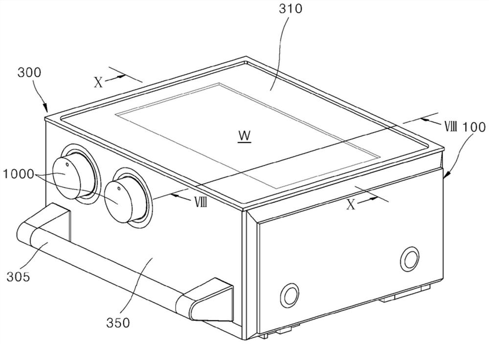
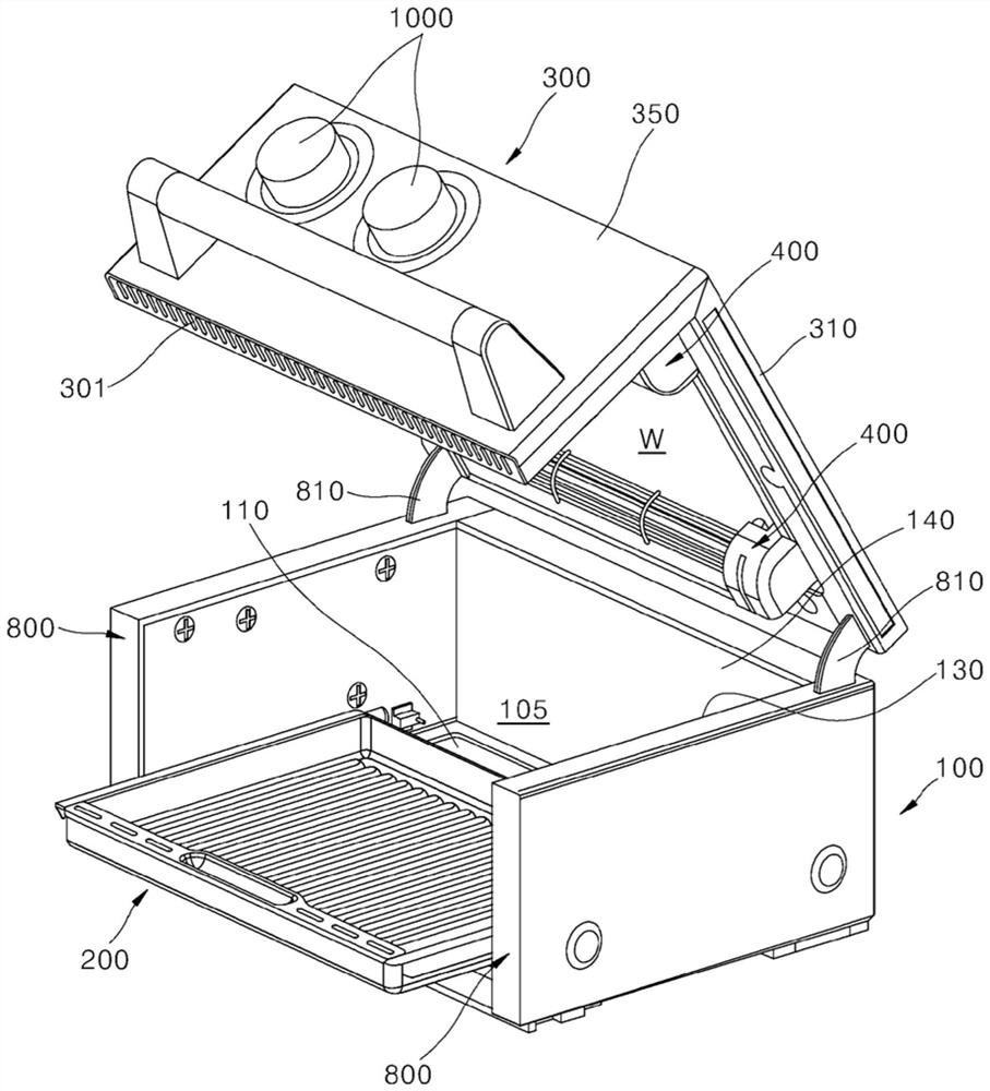
An invention relating to a cooker is disclosed. The disclosed invention is characterized in that the front and upper portions of a housing are opened together when a door is opened, and a tray is pulled out forward in conjunction with the opening of the door.

Description

technical field [0001] The present invention relates to cooking appliances. Background technique [0002] A cooking device is a device that is installed in a kitchen space as one of home appliances for cooking food and cooks food according to a user's intention. Such cooking equipment can be divided into various types according to the heat source or form used and the type of fuel. [0003] If the cooking equipment is classified according to the form of cooking food, it can be divided into open and closed cooking equipment according to the space where the food is placed. Closed cooking equipment includes such as ovens, electromagnetic microwave ovens, etc., and open cooking equipment includes such as cooktops, stove plates, and the like. [0004] A closed cooking device is a cooking device that covers a space where food is located and heats the covered space to cook food. A cooking chamber is provided in a closed cooking device, which is a space that is sheltered when food...

Claims


Application Information

Patent Timeline
Patent Type & Authority Applications(China)
IPC IPC(8): F24C15/04F24C7/06F24C15/02F24C15/00F24C15/16H05B6/12A47J37/06
CPCA47J37/0629F24C7/067F24C15/02F24C15/04F24C15/162F24C7/082H05B6/129F24C15/22F24C7/08H05B6/12
Inventor 尹动赫金学秀郭东星尹星文
Owner LG ELECTRONICS INC
Learn More