A prepreg tape automatic placement head and guide rail bracket

A prepreg tape and laying head technology, applied in the field of automatic laying, can solve the problems of low laying efficiency, only laying layer by layer, sticking and pulling on the surface of the anvil knife and the tape, saving laying time, Improve production efficiency and ensure the effect of laying effect

Active Publication Date: 2022-07-08
CHANGSHA UNIVERSITY OF SCIENCE AND TECHNOLOGY
View PDF0 Cites 0 Cited by
  • Summary
  • Abstract
  • Description
  • Claims
  • Application Information

AI Technical Summary

Problems solved by technology

[0005] 1. The automatic laying technology of the prior art is to lay the prepreg tape layer by layer on the surface of the mold. After laying several layers, the composite material component reaches a certain thickness. Therefore, for laying multi-layer prepreg tape The mold can only be stacked layer by layer, and the laying efficiency is low
[0006] 2. At the end of laying each path, the laying mechanism must go back and forth or turn around to re-lay the previous laying path or lay the next path. Therefore, during the automatic laying process, the laying mechanism needs to Multiple round trips or U-turn laying, wasting a lot of time
[0007] 3. The existing cutting method is the contact cutting of the cutting board and the anvil knife. Since the strip material is moving during the laying process, the contact cutting is easy to cause adhesion and pulling of the anvil knife and the surface of the strip material, which will cause unnecessary damage to the strip material. The tension will affect the laying effect of the tape at the moment of cutting

Method used


Image

  • A prepreg tape automatic placement head and guide rail bracket
  • A prepreg tape automatic placement head and guide rail bracket
  • A prepreg tape automatic placement head and guide rail bracket

Examples


Embodiment Construction

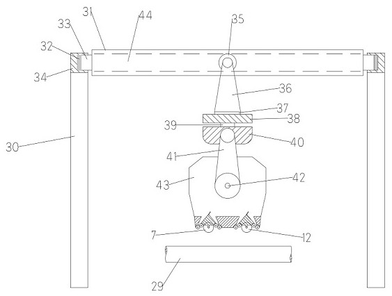
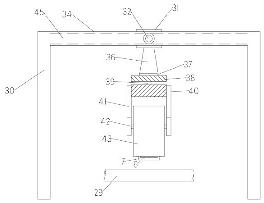
[0035] As shown in the figure: an automatic prepreg tape placement head and a guide rail bracket, the guide rail bracket includes two U-shaped support columns 30, a rolling beam 31 and a placement head fixing device, and the two U-shaped support columns 30 Symmetrically arranged on both sides of the automatic prepreg tape placement head, the top of the U-shaped support column 30 is provided with a bracket guide rail 45, and the rolling beam 31 is fixed to the first rolling wheel 32 through the first connecting shaft 33. , the first rolling wheel 32 can roll in the bracket guide rail 45, the rolling beam 31 is provided with a beam guide rail 44 inside, the prepreg tape automatic laying head is provided with a cover 43 outside, and the cover 43 passes through The placement head fixing device is connected with the rolling beam 31;

[0036] The automatic prepreg tape laying head includes a feeding mechanism, a laying mechanism, a cutting mechanism, a guiding mechanism and a revers...


PUM


Abstract

A prepreg tape automatic laying head and a guide rail bracket, the guide rail bracket includes two U-shaped support columns, a rolling beam and a laying head fixing device, and the two U-shaped support columns are symmetrically arranged on the prepreg tape. On both sides of the automatic placement head, the top of the U-shaped support column is provided with a bracket guide rail, and the rolling beam is fixed to the first rolling wheel through the first connecting shaft, and the first rolling wheel can be installed on the bracket guide rail. In the middle rolling, the rolling beam is provided with a beam guide inside, the prepreg tape automatic laying head is provided with a cover outside, and the cover is connected to the rolling beam through the laying head fixing device, and the prepreg tape automatic laying head Including feeding mechanism, laying mechanism, cutting mechanism, guiding mechanism and reversing mechanism. The automatic laying head of the prepreg tape does not need to be laid layer by layer, which greatly improves the production efficiency.

Description

technical field [0001] The invention relates to the field of automatic laying, in particular to an automatic laying head and a guide rail bracket of a prepreg tape. Background technique [0002] The automatic laying technology has the characteristics of high efficiency, high quality, high reliability and low cost, and is especially suitable for the manufacture of large-sized components, reducing the number of assembled parts, saving manufacturing and assembly costs, and greatly reducing the waste rate of materials It is widely used in the manufacture of aerospace high-performance composite structures. [0003] The automatic laying technology uses the prepreg tape as the raw material. After heating, it is directly laid on the surface of the mold or the upper layer of the prepreg tape under the action of the pressing roller to realize the automatic forming of the composite material laying. [0004] Disadvantages of the prior art: [0005] 1. The automatic laying technology o...

Claims


Application Information

Patent Timeline
Patent Type & Authority Patents(China)
IPC IPC(8): B29C70/38B29C70/54
CPCB29C70/386B29C70/388B29C70/545B29C70/54Y02T50/40
Inventor 张鹏高安康冯文明高远周先锋杨春雨
Owner CHANGSHA UNIVERSITY OF SCIENCE AND TECHNOLOGY
Why Eureka
Try Eureka