

Optical cable fault rapid positioning method based on thermal infrared detection technology
A technology of positioning method and detection technology, which is applied in the direction of testing optical fiber/optical waveguide equipment, measuring devices, optical instrument testing, etc., can solve the problems of high labor cost, low efficiency, and long time-consuming repair process, so as to avoid manpower and resume operation Business, good detection and investigation effect
Pending Publication Date: 2021-08-20
ZHANGZHOU POWER SUPPLY COMPANY STATE GRID FUJIANELECTRIC POWER +1
View PDF0 Cites 0 Cited by
- Summary
- Abstract
- Description
- Claims
- Application Information
AI Technical Summary
Problems solved by technology
[0003] From the analysis of the existing emergency repair of optical cable faults, the average time for troubleshooting and locating fault points in the traditional manual naked eye search mode accounts for half or more of the entire fault repair time, especially at night, in bad weather and other special moments, or when the optical cable line is detoured on the mountain. When the traffic is inconvenient and the environment is more complicated, such as walking between trees, etc., the time will be longer, resulting in long time-consuming, low efficiency and high labor costs for the entire emergency repair process.
Method used
View moreImage
Smart ImageViewing Examples

Examples
Embodiment
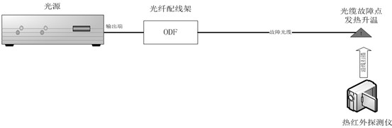
[0035] After an optical cable breakage accident, first use OTDR (Optical Time Domain Reflectometer) to determine the approximate area where the cable breakage point is located, and which fibers are broken in the cable, and then place a high-power Laser (higher power laser) is injected into the faulty fiber to heat the breakpoint of the faulty fiber, and then a thermal infrared detector is used to scan along the cable near the cable breakage to confirm the exact location of the breakpoint of the broken fiber.
Login to View More PUM
 Abstract
The invention provides an optical cable fault rapid positioning method based on a thermal infrared detection technology, which is used to rapidly search the position of a breakpoint of an optical fiber core of a faulty optical cable. The positioning method comprises the following steps of: S1, judging a faulty fiber core with a breakpoint in a faulty optical cable, and preliminarily judging an area where the breakpoint of the fiber core is located so as to carry out troubleshooting; S2, inputting high-power laser into the faulty fiber core at the optical signal access point closest to the breakpoint of the faulty fiber core, so as to increase the temperature of the breakpoint of the faulty fiber core in the optical cable fault area; and S3, searching a high-temperature point in the fault area by adopting a thermal infrared detector so as to accurately position the breakpoint of the faulty fiber core; According to the invention, the efficiency of optical fiber breakpoint troubleshooting can be greatly improved.
Description
technical field [0001] The invention relates to the technical field of optical cable maintenance, in particular to a method for quickly locating optical cable faults based on thermal infrared detection technology. Background technique [0002] The most common faults of the optical cable are the interruption of the optical cable caused by construction breakage, disaster weather, small animal bites, etc. At present, the fault finding of the optical cable is only done by testing the optical cable through OTDR and other instruments to obtain the distance of the fault point, and then relying on manual Large-scale search on the spot with the naked eye. [0003] From the analysis of the existing emergency repair of optical cable faults, the average time for troubleshooting and locating fault points in the traditional manual naked eye search mode accounts for half or more of the entire fault repair time, especially at night, in bad weather and other special moments, or when the opti...
Claims
Login to View More Application Information
Patent Timeline
 IPC IPC(8): G01M11/00H04B10/071
CPCG01M11/30H04B10/071
Inventor钟敏林小平罗正钱阮秋君郭钦源傅昱黄凤珊蔡洪明林逸婷
OwnerZHANGZHOU POWER SUPPLY COMPANY STATE GRID FUJIANELECTRIC POWER