Aqueous humor drainage device for being implanted into eyes of glaucoma patient
A drainage device and glaucoma technology, which is applied in the field of medical devices, can solve the problem of drainage risk that needs to be demonstrated, and achieve the effect of reducing hyphema and improving drainage efficiency.
- Summary
- Abstract
- Description
- Claims
- Application Information
AI Technical Summary
Problems solved by technology
Method used
Image
Examples
Embodiment 1
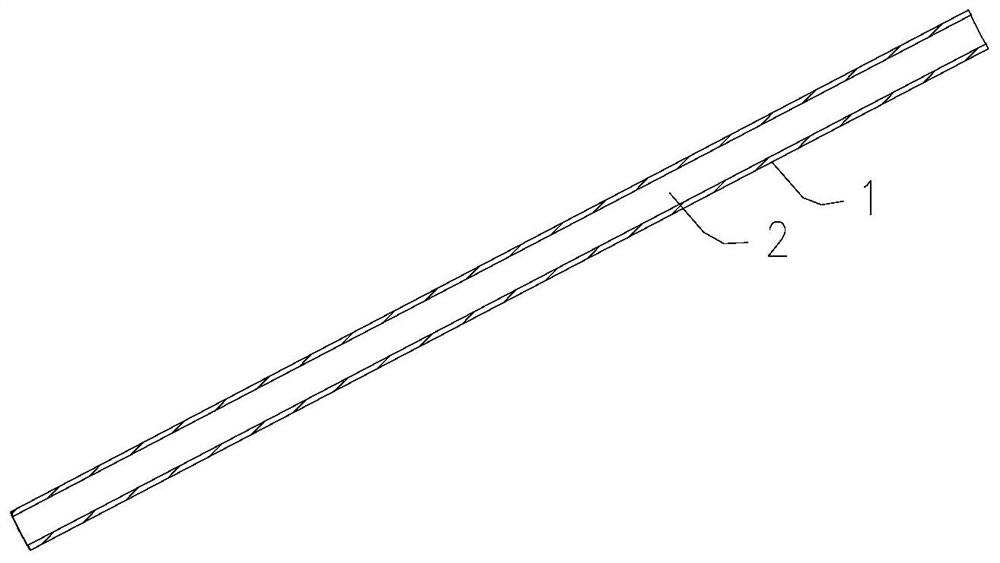
[0054] Such as figure 1 As shown, an aqueous humor drainage device for implanting in the eyes of glaucoma patients, the drainage device 1 is in the shape of a tube as a whole, and a drainage channel 2 is formed in it, which is used to drain the aqueous humor to the filtering tissue, and the drainage channel 2 is equal to Diameter drainage channel.
[0055] In a specific embodiment, the diameter of the drainage channel 1 is 0.03-0.3 mm.
[0056] In a specific embodiment, the axial length of the diverter is 3-15 mm. The axial length of the diverter can be adjusted according to the actual situation.
Embodiment 2
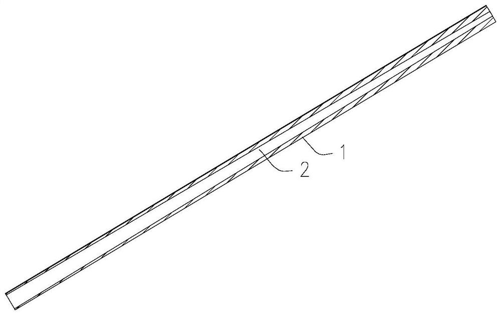
[0058] Such as figure 2 As shown, an aqueous humor drainage device for implanting in the eyes of glaucoma patients, the drainage device 1 is in the shape of a tube as a whole, and a drainage channel 2 is formed in it, which is used to drain the aqueous humor to the filtering tissue. The drainage channel 2 is gradually Expand the diameter of the drainage channel.
[0059] In a specific embodiment, the maximum diameter of the drainage channel 2 is not more than 0.3 mm, and the minimum diameter is not less than 0.03 mm. Wherein, the diameter of the large-diameter end of the drainage channel 2 is 0.05mm-0.3mm, and the diameter of the small-diameter end is 0.03mm-0.15mm. Preferably, the diameter of the large-diameter end of the drainage channel 2 is 0.05mm-0.15mm, and the diameter of the small-diameter end is 0.04mm-0.06mm, which can realize an initial flow rate of 3.5-15 times the rate of aqueous humor production. Dual regulation of venous pressure and pipeline resistance can e...
Embodiment 3
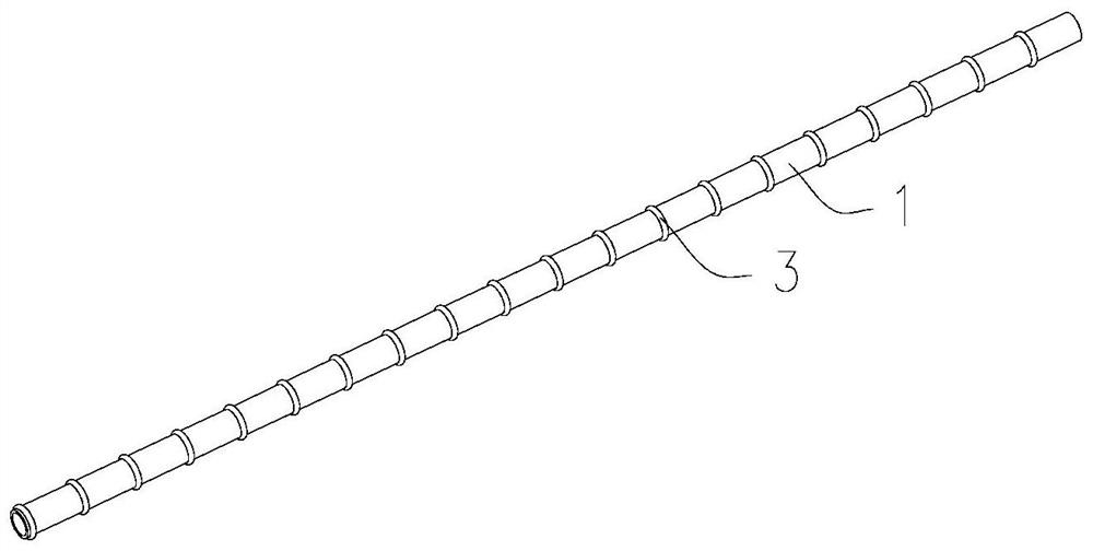
[0062] Others are the same as in Embodiment 1 or Embodiment 2, except that the outer wall of the flow guide is also provided with an auxiliary fixing structure 3 for preventing the axial movement of the flow guide, wherein the auxiliary fixing structure 3 is distributed on the outer wall of the flow guide rings, bumps, ribs, tabs or threaded projections.
[0063] Such as image 3 and Figure 4 As shown, the auxiliary fixing structure 3 is a protruding ring distributed on the outer wall of the flow guide, wherein the protruding rings can be evenly distributed or non-uniformly distributed.
[0064] Such as Figure 5 and Figure 6 As shown, the auxiliary fixing structure 3 is a raised point distributed on the outer wall of the flow guide, wherein the raised points can be evenly distributed on the axial side wall of the flow guide, or can be distributed at one end of the side wall of the flow guide, or can be distributed on the side wall of the flow guide. Anywhere on the side...
PUM
 Abstract
Description
Claims
Application Information
 - R&D
- Intellectual Property
- Life Sciences
- Materials
- Tech Scout
- Unparalleled Data Quality
- Higher Quality Content
- 60% Fewer Hallucinations
Browse by: Latest US Patents, China's latest patents, Technical Efficacy Thesaurus, Application Domain, Technology Topic, Popular Technical Reports.
© 2025 PatSnap. All rights reserved.Legal|Privacy policy|Modern Slavery Act Transparency Statement|Sitemap|About US| Contact US: help@patsnap.com


