A multi-section three-parallel mechanism mechanical arm device that can realize automatic retraction

An automatic retractable and mechanical arm technology, applied in the field of mechanical arms, can solve the problems of slow movement and inability to provide, and achieve the effect of ensuring rapidity

Active Publication Date: 2022-04-08
HARBIN INST OF TECH
View PDF10 Cites 1 Cited by
  • Summary
  • Abstract
  • Description
  • Claims
  • Application Information

AI Technical Summary

Problems solved by technology

[0003] The purpose of the present invention is to solve the problem that the existing mechanical arm mostly adopts multi-axis series mechanism, which has slow movement and cannot provide a large torque limit, and further provides a multi-section three-parallel mechanism that can realize automatic retraction Robotic Arm Device

Method used


Image

  • A multi-section three-parallel mechanism mechanical arm device that can realize automatic retraction
  • A multi-section three-parallel mechanism mechanical arm device that can realize automatic retraction
  • A multi-section three-parallel mechanism mechanical arm device that can realize automatic retraction

Examples


specific Embodiment approach 1

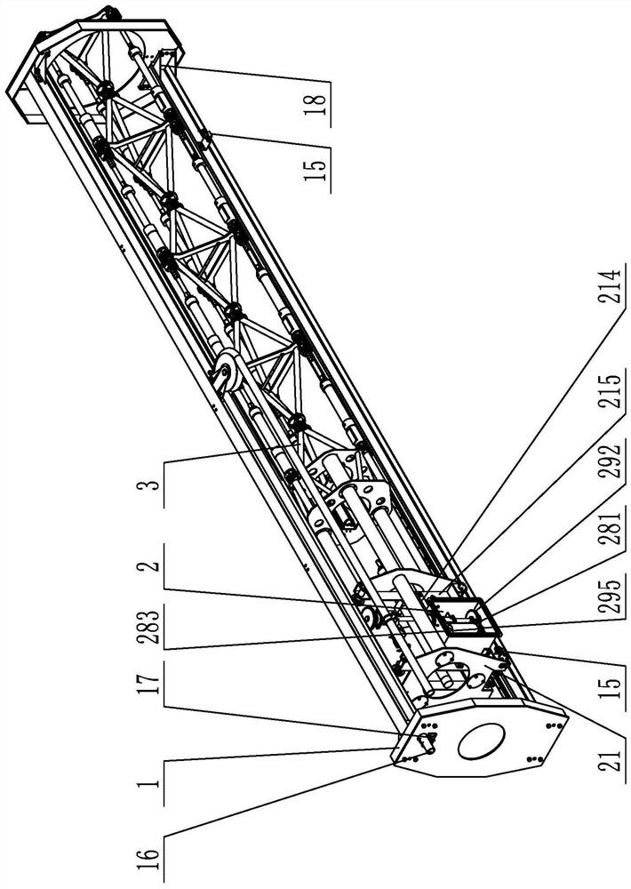
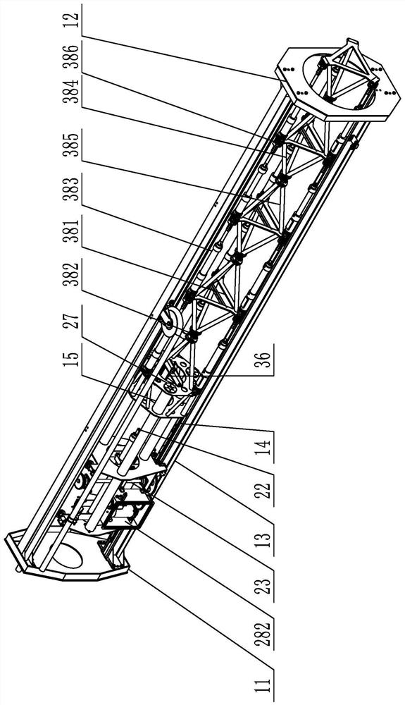
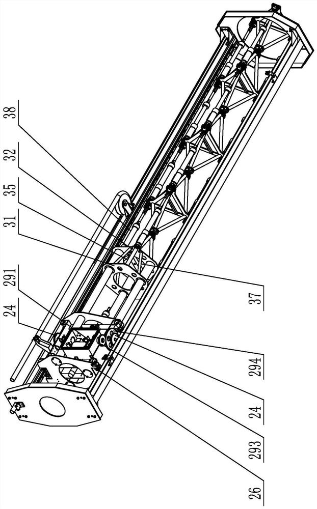
[0024] Specific implementation mode one: combine Figure 1 to Figure 4Describe this embodiment, a multi-section three-parallel mechanical arm device that can realize automatic retraction in this embodiment, it includes a fixed frame 1, a power cabin 2 and a main body of the mechanical arm 3, and the fixed frame 1 includes a tail support Seat 11, front support 12, two guide rails 13 and two tooth racks 14, front support 12 and tail support 11 are relatively horizontally arranged from top to bottom, and two guide rails 13 are relatively vertically arranged on the front support respectively. Between the seat 12 and the tail support 11, and the upper and lower ends of the guide rail 13 are respectively connected with the front support 12 and the inner wall of the tail support 11, and the inner walls of the guide rail 13 on both sides are parallel to the direction of the guide rail 13. A rack 14, the center of the front support 12 is provided with a hole through which the mechanica...

specific Embodiment approach 2

[0027] Specific implementation mode two: combination Figure 1 to Figure 4 To illustrate this embodiment, the fixed frame 1 of this embodiment also includes two limit switches 15, and a guide rail 13 in the fixed frame 1 is provided with two ends of the side walls near the front support 12 and the tail support 11 Two limit switches 15.

[0028] With such an arrangement, the relative position of the power cabin 2 on the guide rails 13 on both sides can be recorded, and cross-border can be prevented. Other compositions and connections are the same as in the first embodiment.

specific Embodiment approach 3

[0029] Specific implementation mode three: combination Figure 1 to Figure 4 To illustrate this embodiment, the fixed frame 1 of this embodiment also includes a hydraulic oil pipe 16 and an oil pipe positioning member 17. The oil pipe positioning member 17 is installed on the outer wall of the tail support 11, and the oil pipe assembly hole is provided on the tail support 11. The hydraulic oil pipe 16 One end passes through the tail support 11 , and the hydraulic oil pipe 16 extends to the outside of the tail support 11 and is connected with the oil pipe positioning member 17 .

[0030] In this way, the oil pipe positioning part 17 is installed on the outer side of the tail support 11 to fix the hydraulic oil pipe 16. The hydraulic oil pipe 16 provides the source power for the whole mechanism. The center of the front support 12 is provided with a hole through which the mechanical arm passes through, which is convenient for the main body of the mechanical arm. 3 stretches out, ...


PUM


Abstract

A multi-section three-parallel mechanical arm device capable of realizing automatic retraction relates to the technical field of mechanical arms. The invention solves the problem that the existing mechanical arm mostly adopts multi-axis series mechanism, which has the limitation of slow movement and inability to provide large torque. The two guide rails of the present invention are relatively arranged between the front support and the tail support, two racks are oppositely arranged on the inner walls of the guide rails on both sides, and two support webs are relatively arranged between the upper support plate and the lower support plate In between, the servo hydraulic cylinder is installed on the shell of the power cabin, the execution ladder shaft is installed on two support webs, the execution gear installed at both ends of the execution ladder shaft meshes with the racks on both sides, and the servo hydraulic cylinder connector is installed on the front seat Above, the connecting piece of the servo hydraulic cylinder is connected with the piston rod of the servo hydraulic cylinder, and the main body of the extended arm passes through the mechanical arm of the front support to connect with the front seat through the hole. The present invention can ensure the quickness of the overall movement of the mechanical arm, and can also ensure the required torque when grasping large-mass objects.

Description

technical field [0001] The invention relates to the technical field of mechanical arms, in particular to a multi-section three-parallel mechanical arm device capable of automatic retraction. Background technique [0002] The robotic arm is an important industrial device, which is widely used in industry, aerospace, military, medical, service and other fields. The robotic arm can be used to grasp and release large-mass objects, and plays a very important role in industrial production. important role. Traditional robotic arms mostly use multi-axis series mechanisms. This solution has a simple structure and is easy to operate and control, but it has the problem of slow movement and the limitation of not being able to provide a large torque. Contents of the invention [0003] The purpose of the present invention is to solve the problem that the existing mechanical arm mostly adopts multi-axis series mechanism, which has slow movement and cannot provide a large torque limit, a...

Claims


Application Information

Patent Timeline
Patent Type & Authority Patents(China)
IPC IPC(8): B25J9/00B25J9/14
CPCB25J9/003B25J9/144
Inventor 查富生郭伟王鹏飞李满天文继宏陶建国
Owner HARBIN INST OF TECH
Why Eureka
Try Eureka