Joint flaring shaping device for flush type plastic pipes

A plastic pipe and shaping device technology, which is applied to machine tools, grinders, and metal processing equipment suitable for grinding the edge of workpieces, can solve problems such as manual grinding, difficulty in flaring, and reduced airtightness of plastic pipes, so as to avoid warping , easy to use, and the effect of improving construction efficiency

Active Publication Date: 2021-08-24
东营金昱技术开发有限公司
View PDF9 Cites 0 Cited by
  • Summary
  • Abstract
  • Description
  • Claims
  • Application Information

AI Technical Summary

Problems solved by technology

[0002] In the prior art, plastic pipes (such as pvc pipes) or plastic composite pipes are widely used in oil exploration, oil and gas transportation, chemical material transportation, and water transportation. However, when laying plastic pipes, the flared plastic pipes used to connect other plastic pipes When the pipe is long, it needs to be cut off by the staff, and then re-flared; because the existing flaring equipment is large in size, it is not convenient to use outdoors, and manual flaring is often used; It is long and thick, and flaring is difficu

Method used


Image

  • Joint flaring shaping device for flush type plastic pipes
  • Joint flaring shaping device for flush type plastic pipes
  • Joint flaring shaping device for flush type plastic pipes

Examples


Embodiment 1

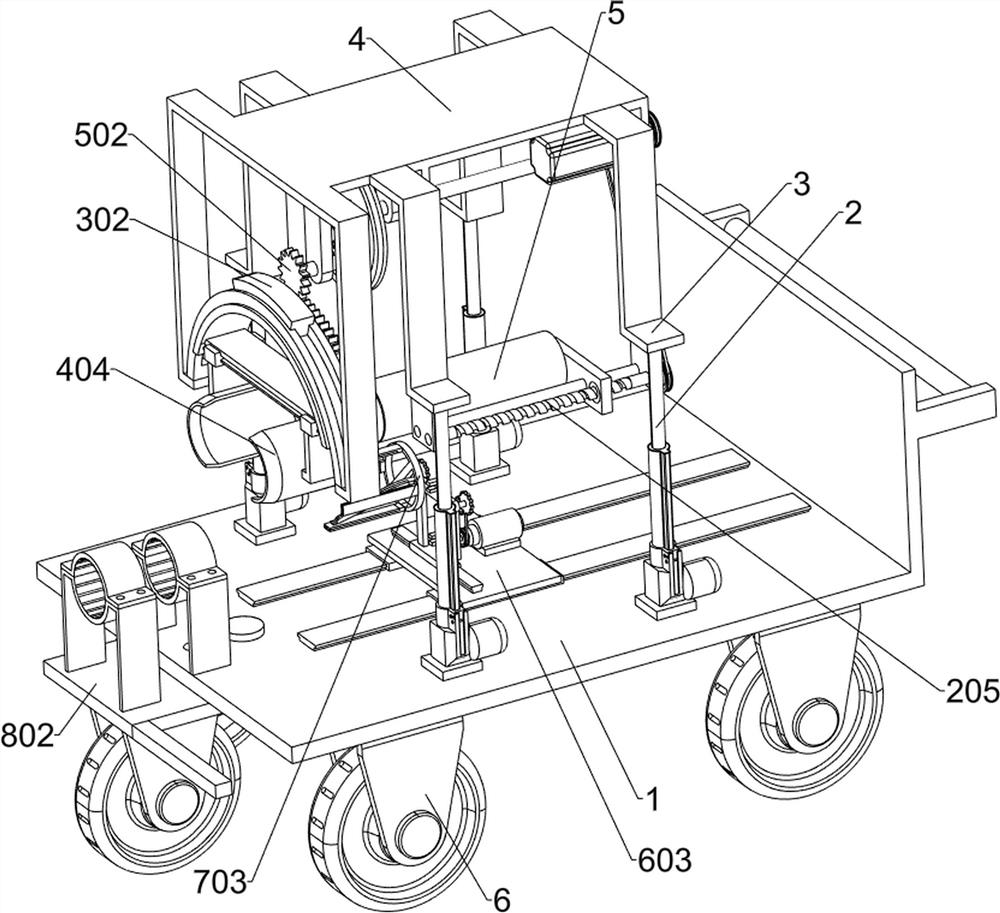
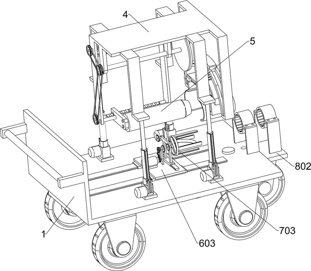
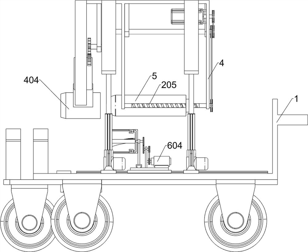
[0040] A flaring and shaping device for joints of flush plastic pipes, such as Figure 1-9 As shown, it includes a vehicle frame 1, a driving member 2, a first connecting plate 3, a flaring frame 4, a flaring device 5, a first traveling wheel 6, a flaring driving mechanism, a reciprocating rotation mechanism and a pipe clamping mechanism; Four groups of driving parts 2 are symmetrically installed on the vehicle frame 1; the tops of the movable rods of the four groups of driving parts 2 are fixedly connected with a group of first connecting plates 3; The port frame 4 includes a horizontal plate 41, a first vertical plate 42, a second vertical plate 43, a third vertical plate 44, a fourth vertical plate 45, a fifth vertical plate 46, a sixth vertical plate 47 and a seventh vertical plate 48; the left rear side of the horizontal plate 41 of the flared frame 4 is connected with the first vertical plate 42; the left front side of the horizontal plate 41 of the flared frame 4 is con...

Embodiment 2

[0051] Such as figure 1 with Figure 17-19As shown, a support mechanism is also included, and the support mechanism includes a guide U-shaped plate 801, a support plate 802, a push rod 803, an insertion rod 804, a second traveling wheel 805, a first clamping assembly and a second clamping assembly; Two sets of symmetrically distributed guide U-shaped plates 801 are connected by bolts on the lower surface of the frame 1; a support plate 802 is slidingly connected between the two sets of guide U-shaped plates 801; a push rod 803 is fixedly connected to the left side of the support plate 802; There are at least two jacks on the support plate 802, the support plate 802 is inserted with an insertion rod 804 through the jack, and the vehicle frame 1 is inserted into the insertion rod 804 through the jack; the left side of the support plate 802 lower surface is fixedly connected with a The second traveling wheel 805; the first clamping assembly is installed on the left side of the u...

Embodiment 3

[0056] Such as figure 1 with Figure 10-16 As shown, a burr removal mechanism is also included, and the burr removal mechanism includes a second electric slide rail 601, a second electric slider 602, a third connecting plate 603, a second motor 604, a fourth connecting plate 605, and a fourth pulley 606 , the third rotating rod 607, the fifth pulley 608, the third gear 609, the third electric slide rail 610, the third electric slider 611, the connecting frame 612, the fourth rotating rod 613, the fourth gear 614, the connecting rod 615 and Grinder 616; two sets of second electric slide rails 601 symmetrically distributed are installed above the vehicle frame 1; two sets of second electric slide rails 601 are slidingly connected with a set of second electric slide blocks 602 on the outer surfaces; two sets of second electric slide rails A third connecting plate 603 is fixedly connected above the block 602; a second motor 604 is fixedly connected on the right side above the thi...


PUM


Abstract

The invention relates to the technical field of plastic pipe machining, in particular to a joint flaring shaping device for flush type plastic pipes. The technical problem to be solved by the invention is that when the plastic pipes are flared, the edges tilt. According to the technical scheme, the joint flaring shaping device for the flush type plastic pipes comprises a flaring driving mechanism, a reciprocating rotating mechanism, a pipe clamping mechanism and the like; and a flaring device is mounted on a moving part of the flaring driving mechanism. According to the device, the plastic pipes can be flared outdoors, the flared parts of the plastic pipes can be clamped and limited, the plastic pipes are prevented from tilting, when the flared parts of the plastic pipes tilt, the tilting parts of the plastic pipes are in contact through reciprocating friction, the plastic pipes are transferred towards the two sides, the defect that the flared parts of the plastic pipes are extruded to be stacked together when the flared parts of the plastic pipes tilt, so that the plastic pipes deform is overcome, and the construction efficiency of pipelines can be greatly improved.

Description

technical field [0001] The invention relates to the technical field of plastic pipe processing, in particular to a flat-type plastic pipe joint flaring and shaping device. Background technique [0002] In the prior art, plastic pipes (such as pvc pipes) or plastic composite pipes are widely used in oil exploration, oil and gas transportation, chemical material transportation, and water transportation. However, when laying plastic pipes, the flared plastic pipes used to connect other plastic pipes When the pipe is long, it needs to be cut off by the staff, and then re-flared; because the existing flaring equipment is large in size, it is not convenient to use outdoors, and manual flaring is often used; It is long and thick, and flaring is difficult, which causes the edge of the plastic pipe to warp, which in turn reduces the sealing between the plastic pipes and even leaks the material liquid; at the same time, the section of the plastic pipe used for temporary flaring after ...

Claims


Application Information

Patent Timeline
IPC IPC(8): B29C57/04B29C37/02B24B9/00B24B9/20
CPCB24B9/007B24B9/20B29C37/02B29C57/04
Inventor 江海瑛
Owner 东营金昱技术开发有限公司
Why Eureka
Try Eureka