Splicing device for PE pipes

A splicing device and a practical technology, applied in applications, tubular objects, household appliances, etc., can solve problems such as affecting the sealing performance of PE pipes, affecting the normal use of PE pipes, and loose connections

Active Publication Date: 2021-08-24
山东中科欧普管道有限公司
View PDF43 Cites 0 Cited by
  • Summary
  • Abstract
  • Description
  • Claims
  • Application Information

AI Technical Summary

Problems solved by technology

[0002] When it is necessary to use PE pipes in engineering construction, some sizes are not enough, some are too long, and those that are too long can be cut off, but those that are not enough in size can only be spliced ​​with short PE pipes. When splicing, use There are many methods, some of which are locked with locks between them. Long-term fastening will make the connection loose, which will affect the sealing of the connection between PE pipes, and it is easy to cause leakage of PE pipes. This will affect the normal use of PE pipes, and when using hot-melt connections, it is generally necessary to use joints to connect, and when connecting PE pipes, the length of the connection is not easy to control, which will make the connection The stability is poor, thus It will also cause water leakage in PE pipes. Therefore, it is urgent to design a splicing device for PE pipes to solve the connection problem of PE pipes.

Method used


Image

  • Splicing device for PE pipes
  • Splicing device for PE pipes
  • Splicing device for PE pipes

Examples


Embodiment Construction

[0017] The following will clearly and completely describe the technical solutions in the embodiments of the present invention with reference to the accompanying drawings in the embodiments of the present invention. Obviously, the described embodiments are only some, not all, embodiments of the present invention. Based on the embodiments of the present invention, all other embodiments obtained by persons of ordinary skill in the art without making creative efforts belong to the protection scope of the present invention.

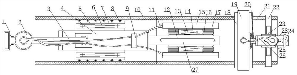
[0018] see Figure 1-3 , the present invention provides a technical solution:

[0019] A splicing device for PE pipes, comprising a first pipe body 10 and a second pipe body 21, the first pipe body 10 is covered with a first hydraulic cylinder 4, and a handle is fixedly installed on the left side of the first hydraulic cylinder 4 surface Rod 3, the handle 1 is fixedly installed on the left end of the grip rod 3, the first air pump 2 is fixedly installed on th...


PUM


Abstract

The invention aims to solve the splicing problem of PE pipes, and discloses a splicing device for the PE pipes. The splicing device comprises a first pipe body and a second pipe body, a first hydraulic cylinder is sleeved with the first pipe body, a holding rod is fixedly mounted at the left side of the surface of the first hydraulic cylinder, a handle is fixedly mounted at the left end of the holding rod, a first air pump is fixedly installed at the left side of the surface of the holding rod, a guide ring is fixedly installed at the right side of the surface of the first hydraulic cylinder, first spiral springs are symmetrically connected to the two side faces of the first hydraulic cylinder, first sliding rods are sleeved with the first spiral springs, and a top plate is installed at the outer ends of the first sliding rods; and guide wheels are evenly installed on the outer surface of the top plate, a first piston rod is installed at the right side of the first hydraulic cylinder, and a heating strip is fixedly installed in the middle of the side face of the first piston rod. By means of the splicing device, tension is provided for the inner walls of the PE pipes through an adhesion layer, and then extrusion force is provided for the PE pipes through an air bag ring, so that splicing of the PE pipes is conveniently achieved so as to meet different requirements.

Description

technical field [0001] The invention relates to the field of PE pipe connection, in particular to a splicing device for PE pipes. Background technique [0002] When it is necessary to use PE pipes in engineering construction, some sizes are not enough, some are too long, and those that are too long can be cut off, but those that are not enough in size can only be spliced ​​with short PE pipes. When splicing, use There are many methods, some of which are locked with locks between them. Long-term fastening will make the connection loose, which will affect the sealing of the connection between PE pipes, and it is easy to cause leakage of PE pipes. This will affect the normal use of PE pipes, and when using hot-melt connections, it is generally necessary to use joints to connect, and when connecting PE pipes, the length of the connection is not easy to control, which will make the connection The stability is poor, thus It will also cause water leakage in the PE pipe. Therefore,...

Claims


Application Information

Patent Timeline
Patent Type & Authority Applications(China)
IPC IPC(8): B29C65/02B29C65/50B29C65/78B29L23/00
CPCB29C65/02B29C65/50B29C65/7841B29C66/5221B29L2023/22Y02A20/20
Inventor 朝格毕力格
Owner 山东中科欧普管道有限公司
Why Eureka
Try Eureka