Electric driving structure of vehicle door and vehicle
An electric drive and door technology, applied in the direction of power control mechanism, wing leaf control mechanism, door/window accessories, etc., can solve the problems of high cost and complex structure, and achieve lightweight reduction, shortened transmission chain, and easy layout Effect
- Summary
- Abstract
- Description
- Claims
- Application Information
AI Technical Summary
Problems solved by technology
Method used
Image

Examples
Embodiment Construction
[0027] In order to make the technical problems, technical solutions and beneficial effects solved by the present invention clearer, the present invention will be further described in detail below in conjunction with the accompanying drawings and embodiments. It should be understood that the specific embodiments described here are only used to explain the present invention, not to limit the present invention.
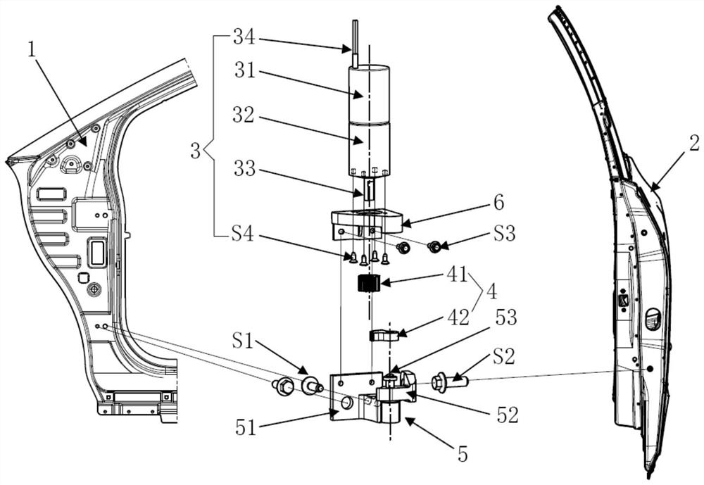
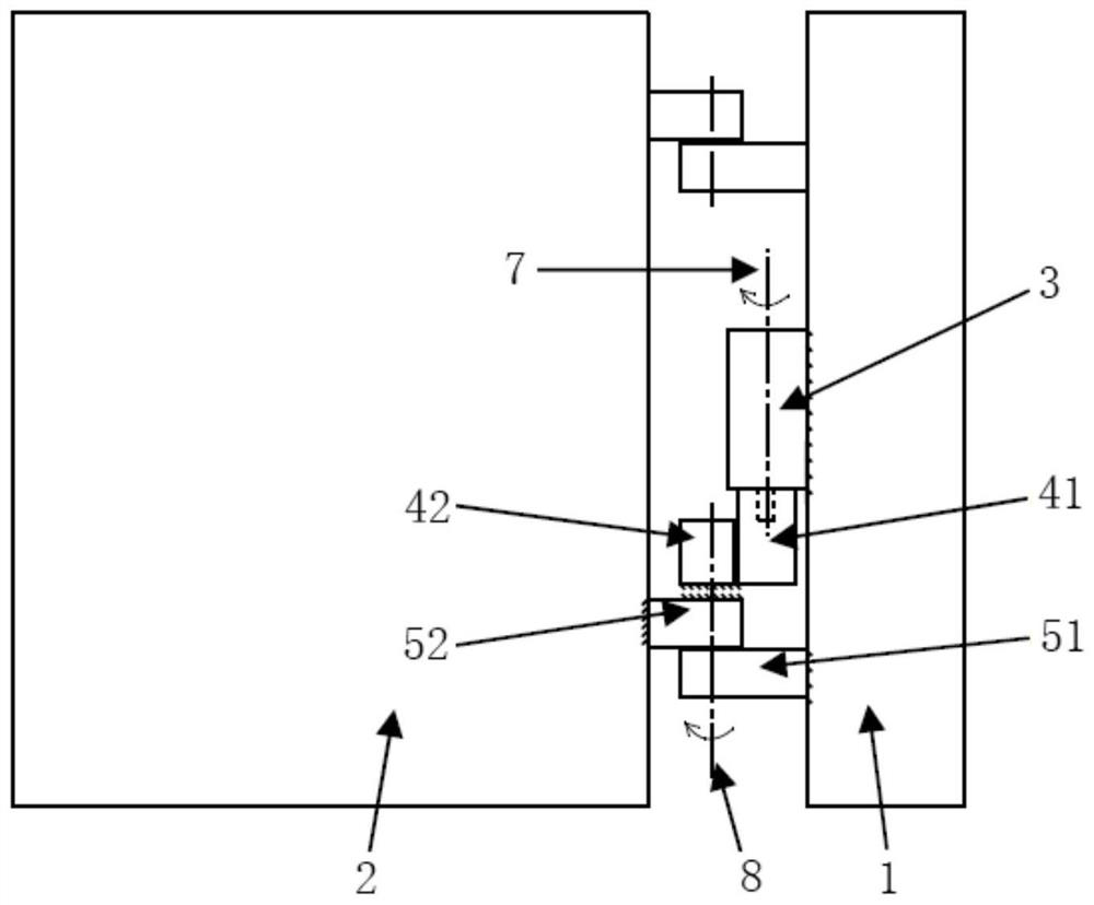
[0028] Such as Figure 1 to Figure 2 As shown, an electric drive structure for a car door provided by an embodiment of the present invention includes a power unit 3, a transmission mechanism 4 and a hinge 5;
[0029] The hinge 5 includes a fixed leaf 51 and a movable leaf 52 that is rotatably connected to the fixed leaf 51. The movable leaf 52 can be rotatably connected to the fixed leaf 51 through a rotating shaft 53; the fixed leaf 51 is fixed on the vehicle body 1, and the movable leaf 52 is fixed on the door 2 ;
[0030] The power unit 3 is fixed on the body 1, spe...
PUM
 Abstract
Description
Claims
Application Information
 - R&D
- Intellectual Property
- Life Sciences
- Materials
- Tech Scout
- Unparalleled Data Quality
- Higher Quality Content
- 60% Fewer Hallucinations
Browse by: Latest US Patents, China's latest patents, Technical Efficacy Thesaurus, Application Domain, Technology Topic, Popular Technical Reports.
© 2025 PatSnap. All rights reserved.Legal|Privacy policy|Modern Slavery Act Transparency Statement|Sitemap|About US| Contact US: help@patsnap.com