A wave energy power generation device and amplifying mechanism under low energy flow density
A technology of a power generation device and amplifying mechanism, which is applied in the directions of ocean energy power generation, hydropower generation, engine components, etc., can solve the problem that the wave energy power generation device is not suitable for the sea area with low energy flow density, and achieves the improvement of wave energy conversion efficiency, ease of construction, and cost. low cost effect
- Summary
- Abstract
- Description
- Claims
- Application Information
AI Technical Summary
Problems solved by technology
Method used
Image
Examples
Embodiment 1
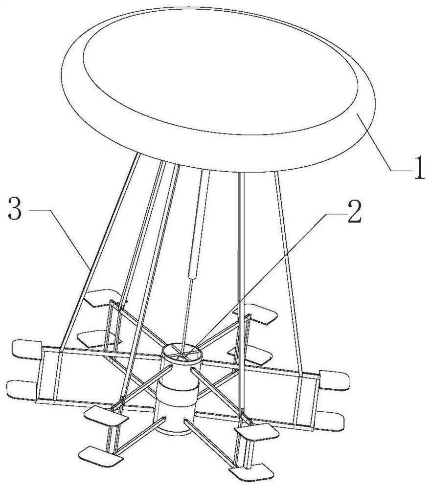
[0054] Such as figure 1 As shown, the wave energy generating device of this embodiment includes an energy harvesting component 1 , a conversion mechanism 2 and an amplification mechanism 3 . The conversion mechanism 2 is arranged directly below the energy harvesting part 1, that is, the axis of the conversion mechanism 2 coincides with the axis of the energy harvesting part 1; one end of the amplification mechanism 3 is hinged to the lower part of the energy harvesting part 1, and the other end is connected to the external hinge;
[0055] A plurality of amplifying mechanisms 3 are evenly distributed at equal angles to the axes of the energy harvesting component 1 and the conversion mechanism 2, and in this embodiment, six amplifying mechanisms are evenly distributed at equal angles. When the energy harvesting component 1 is heaving under the action of waves, the energy harvesting component 1 will lift or lower the conversion mechanism 2 through the amplification mechanism 3, ...
Embodiment 2
[0067] Such as Figure 5 shown as figure 1 The structure diagram of the device, in order to further increase the stability of the device, the Figure 4 The enlargement mechanism 3 in carries out the expansion of parallelogram mechanism, is exactly this embodiment figure 1 organization diagram. The amplifying mechanism 3 here includes not only a pull rod 301, a link arm 302 and a damping plate 303, but also a link 304; the number of link arms 302 is two, arranged in parallel up and down, and the two ends of the link 304 are respectively connected The two link arms 302 and two damping plates 303 are respectively hinged to one end of the two parallel link arms 302, and the two damping plates 303 are fixedly connected together.
[0068] but Figure 5 In the mechanism shown, the hinges at both ends of the two link arms 302 constitute a parallelogram mechanism, the hinge at the right side of the damping plate 303 and the link arms 302 is no longer a local degree of freedom, and ...
Embodiment 3
[0072] Such as Image 6 As shown, this institution is Figure 4 A further modification of the mechanism is to adopt more link arms 302 to be arranged in parallel, and to arrange several link arms 304 between the link arms 302 arranged in parallel. According to the characteristics of the parallelogram mechanism, all links 304 and more than 2 The connecting rod arms 302 are all virtual constraints, which can be omitted when calculating the degrees of freedom, that is to say, the connecting rod 304 may not be set when the device is designed, and when the connecting rod 304 is set, several damping plates may not be connected into one body, When the connecting rod 304 is not provided, several damping plates need to be connected into one body.
[0073] After the micro-amplitude wave acts on the energy harvesting component 1, it will cause a small displacement movement of the energy harvesting component 1, but under the action of the amplification mechanism 3, the linear motion disp...
PUM
 Abstract
Description
Claims
Application Information
 - R&D
- Intellectual Property
- Life Sciences
- Materials
- Tech Scout
- Unparalleled Data Quality
- Higher Quality Content
- 60% Fewer Hallucinations
Browse by: Latest US Patents, China's latest patents, Technical Efficacy Thesaurus, Application Domain, Technology Topic, Popular Technical Reports.
© 2025 PatSnap. All rights reserved.Legal|Privacy policy|Modern Slavery Act Transparency Statement|Sitemap|About US| Contact US: help@patsnap.com


