
Torque wrench calibrating instrument and calibrating method thereof

A technology of torque wrench and calibrator, applied in the field of torque wrench, can solve problems such as low efficiency, achieve high sensitivity, improve verification efficiency, and improve work efficiency.

Pending Publication Date: 2021-08-24
SHAANXI JOIN CREATE SCI & TECH
View PDF0 Cites 2 Cited by
  • Summary
  • Abstract
  • Description
  • Claims
  • Application Information

AI Technical Summary

Problems solved by technology

[0005] A torque wrench calibrator provided by the invention solves the problem of low efficiency caused by traditional manual detection

Method used


Image

  • Torque wrench calibrating instrument and calibrating method thereof
  • Torque wrench calibrating instrument and calibrating method thereof
  • Torque wrench calibrating instrument and calibrating method thereof

Examples


Embodiment 1

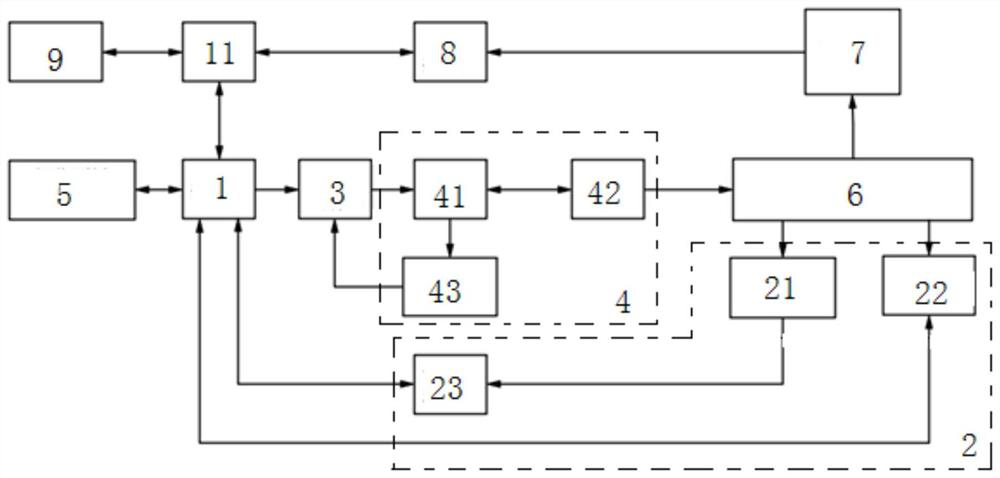
[0051] Embodiment 1 of the present invention provides a torque wrench calibrator, such as figure 1 As shown, it includes control assembly 1, data acquisition assembly 2, drive assembly 3, deceleration assembly 4, display assembly 5 and output shaft sleeve connector 6; the data acquisition assembly 2, drive assembly 3 and display assembly 5 are all connected to the control Component 1 is connected, the control component 1, drive component 3, deceleration component 4 and output shaft sleeve connector 6 are connected in sequence, one end of the output shaft sleeve connector 6 is connected with a torque wrench 7 with verification, and the other One end is connected with the data acquisition component 2;

[0052] In this way, with the above structure, the control assembly 1 receives external instructions and transmits them to the drive assembly 3, and the drive assembly 3 drives the deceleration assembly 4 to work according to the external instructions, and outputs the final torque...

Embodiment 2

[0093] Embodiment 2 of the present invention provides a verification method of a torque wrench verification instrument, which divides the range of the torque wrench 7 with verification into N shorts, that is, N times of loading, corresponding to N verification points, and the verification of each verification point includes the following step:

[0094] S1, initialize the torque wrench 7 with verification;

[0095] S2, inputting an external command;

[0096]S3, the control component 1 automatically sets the torque upper limit, automatically sets the rotation angle upper limit, automatically sets the loading rate, and automatically divides the test points according to the range according to the external command; and converts them into motor operation parameters;

[0097] S4, the drive assembly 3 controls the deceleration assembly 4 to work according to the parameters in S3;

[0098] S5, the data collection component 2 collects the torque of the verified torque wrench 7 in real...


PUM


Abstract

The invention discloses a torque wrench calibrating instrument and a calibrating method thereof. The calibrating instrument comprises a control assembly, a data acquisition assembly, a driving assembly, a speed reduction assembly, a display assembly and an output shaft sleeve connector. The data acquisition assembly, the driving assembly and the display assembly are all connected with the control assembly. The control assembly, the driving assembly, the speed reduction assembly and the output shaft sleeve connector are sequentially connected, one end of the output shaft sleeve connector is connected with a torque wrench to be calibrated, and the other end of the output shaft sleeve connector is connected with the data acquisition assembly. When the calibrating instrument is used, the control assembly receives an external instruction and transmits the external instruction to the driving assembly, the driving assembly drives the speed reduction assembly to work according to the external instruction, and the final torque of the torque wrench to be calibrated is output to the output shaft sleeve connector. The final torque is transmitted to the control assembly through the data acquisition assembly and is displayed through the display assembly, traditional manual verification is replaced by an automatic mode, and the working efficiency is improved.

Description

technical field [0001] The invention belongs to the technical field of torque wrench, and in particular relates to a torque wrench calibrating instrument and a calibrating method thereof. Background technique [0002] Torque wrench is an important measuring instrument for product quality control in the assembly industry, and an important cornerstone of thread bolt torque process quality assurance. It is widely used in petrochemical, aerospace, shipbuilding, automobile, precision machinery and precision instrument manufacturing. [0003] In view of the increasingly prominent losses caused to enterprises due to problems such as torque failure this year, most engineering assembly industries have adopted torque wrenches with pointers or digital displays, which has alleviated problems such as torque control failure to a certain extent. [0004] However, the accuracy of torque wrenches used in large quantities will be affected by many factors after long-term use. In order to ensur...

Claims


Application Information

Patent Timeline
Patent Type & Authority Applications(China)
IPC IPC(8): G01L25/00
CPCG01L25/003
Inventor 马歆彭琰举
Owner SHAANXI JOIN CREATE SCI & TECH
Learn More