Wire stator electrodip paint heating system

A heating system, wire stator technology, applied in electric heating devices, manufacturing stator/rotor bodies, electromechanical devices, etc., can solve the problems of complex automatic heating program design, and achieve low power factor, compensation for reactive power, and reduction of production costs. Effect

Pending Publication Date: 2021-08-24
WOLONG ELECTRIC GRP CO LTD
View PDF0 Cites 0 Cited by
  • Summary
  • Abstract
  • Description
  • Claims
  • Application Information

AI Technical Summary

Problems solved by technology

[0004] Aiming at the complicated technical problem of automatic heating program design, the present invention provides a wire stator electric varnish heating system, which is very simple in program design and can effectively reduce production costs

Method used


Image

  • Wire stator electrodip paint heating system
  • Wire stator electrodip paint heating system
  • Wire stator electrodip paint heating system

Examples


Embodiment 1

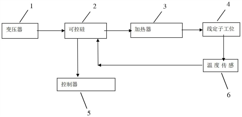
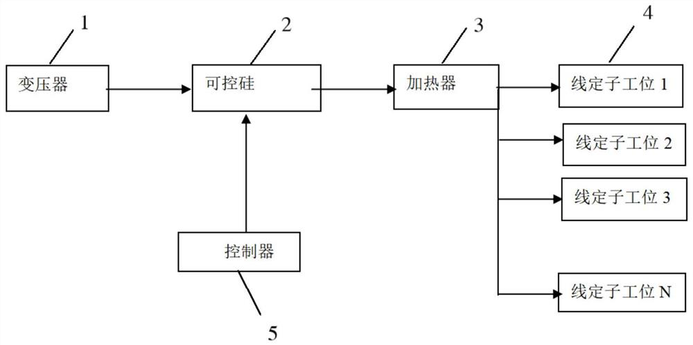
[0026] combined with Figure 1-2 , a wire stator electric varnish heating system in this embodiment includes a transformer 1, a thyristor 2, a heater 3 and a plurality of wire stator stations 4 connected in sequence, the transformer 1 is used to output power, and the The thyristor 2 is used to control the heater 3 to heat the wire stator installed on the wire stator station 4, the thyristor 2 is connected with a controller 5, and the controller 5 is used to store the thyristor 2 pairs of wires Control steps for stator heating. The thyristor 2 records the control steps of heating the wire stator in the controller 5, and the thyristor 2 reads the control program previously stored in the controller 5 and applies it to the heater 3. When there are multiple wires When the stator station is 4, each wire stator station 4 will be loaded with a current that conforms to the control program of the controller 5 to achieve the purpose of temperature control. The program design is very sim...

Embodiment 2

[0028] combined with Figure 1-2 , the wire stator electric dipping paint heating system of this embodiment, compared with the technical solution of embodiment 1, can be improved as follows: the wire stator station 4 is provided with a temperature sensor 6, and the temperature sensor 6 is used to convert the temperature signal Transfer to SCR 2. The embedded temperature sensor 6 on the wire stator feeds back the signal to the thyristor 2, and the thyristor 2 controls the heater 3 after receiving the signal, so as to achieve the purpose of heating the wire stator.

Embodiment 3

[0030] combined with Figure 1-2 Compared with the technical solution of Embodiment 1 or 2, the wire stator electric varnish heating system of this embodiment can be improved as follows: a filter is also included, and the filter is used for harmonic compensation of the transformer 1 . The filter effectively filters out the frequency point of a specific frequency in the power line or frequencies other than this frequency point to obtain a power signal of a specific frequency.


PUM


Abstract

The invention discloses a wire stator electrodip paint heating system, and relates to the technical field of motors. The system comprises a transformer, a silicon controlled rectifier, a heater and a plurality of wire stator stations which are connected in sequence; the transformer is used for outputting a power supply, and the silicon controlled rectifier is used for controlling the heater to heat wire stators installed on the wire stator stations. The silicon controlled rectifier is connected with a controller, and the controller is used for storing control steps of heating the wire stator by the silicon controlled rectifier. The silicon controlled rectifier records the control step of heating the wire stator in the controller, reads a control program stored in the controller and applies the control program to the heater, and when a plurality of wire stator stations exist, each wire stator station is loaded with current conforming to the control program of the controller so as to achieve the purpose of temperature control. The program design is very simple, and the production cost can be effectively reduced.

Description

technical field [0001] The invention relates to the technical field of motors, in particular to a wire stator electric dipping paint heating system. Background technique [0002] The motor is a device that converts electrical energy into kinetic energy. Motors are widely used in the home appliance industry, such as fans and mixers. With the improvement of people's living standards, household appliances are becoming more and more diverse, and the demand for motors is also increasing. The motor is composed of a stator and a rotor. The stator needs to be heated before dipping the paint. The number of stations used to install the stator is small, the efficiency is not high, and the design of the automatic heating program is relatively complicated, and the production cost is high. Contents of the invention [0003] 1. The technical problem to be solved by the invention [0004] Aiming at the technical problem of complex automatic heating program design, the invention provides ...

Claims


Application Information

Patent Timeline
Patent Type & Authority Applications(China)
IPC IPC(8): H02K15/12H02K15/02B05C9/14H05B1/02G06F17/14H02J3/01H02J3/18
CPCB05C9/14G06F17/14H02J3/01H02J3/18H02K15/02H02K15/12H05B1/023Y02E40/30Y02E40/40Y02P70/10
Inventor 王浙栋汪全浩李琼
Owner WOLONG ELECTRIC GRP CO LTD
Why Eureka
Try Eureka