Conveyor system

Inactive Publication Date: 2005-01-25
MITSUBISHI ELECTRIC CORP
View PDF22 Cites 5 Cited by
  • Summary
  • Abstract
  • Description
  • Claims
  • Application Information

AI Technical Summary

Benefits of technology

In the conveying apparatus arranged above-described according to this invention, the infinite rotation control capable of arbitrarily setting a rotation number ratio R between a rotation number N of the drive and a rotation number M of the rotary shaft, and positioning every time at a predetermined angle becomes possible. As a result, an advantage is performed such that any extra operation can be omitted, and the program becomes simple.
In addition, even when applying to a linear-moving shaft such as used in a conveyor, an operation ratio R between the rotation number N of the drive and a moving distance Mmm of the linear-moving shaft can be set arbitrarily. As a result, an advantage is performed su

Problems solved by technology

However, a problem exists in that setting below the resolution is impossible, and that conduction of conveying work repeatedly brings about an accumulated error, making it impossible to carry out an exact conveying work.
Therefore, a problem exists in that conduction of any conveying

Method used


Image

  • Conveyor system
  • Conveyor system
  • Conveyor system

Examples


embodiment 1

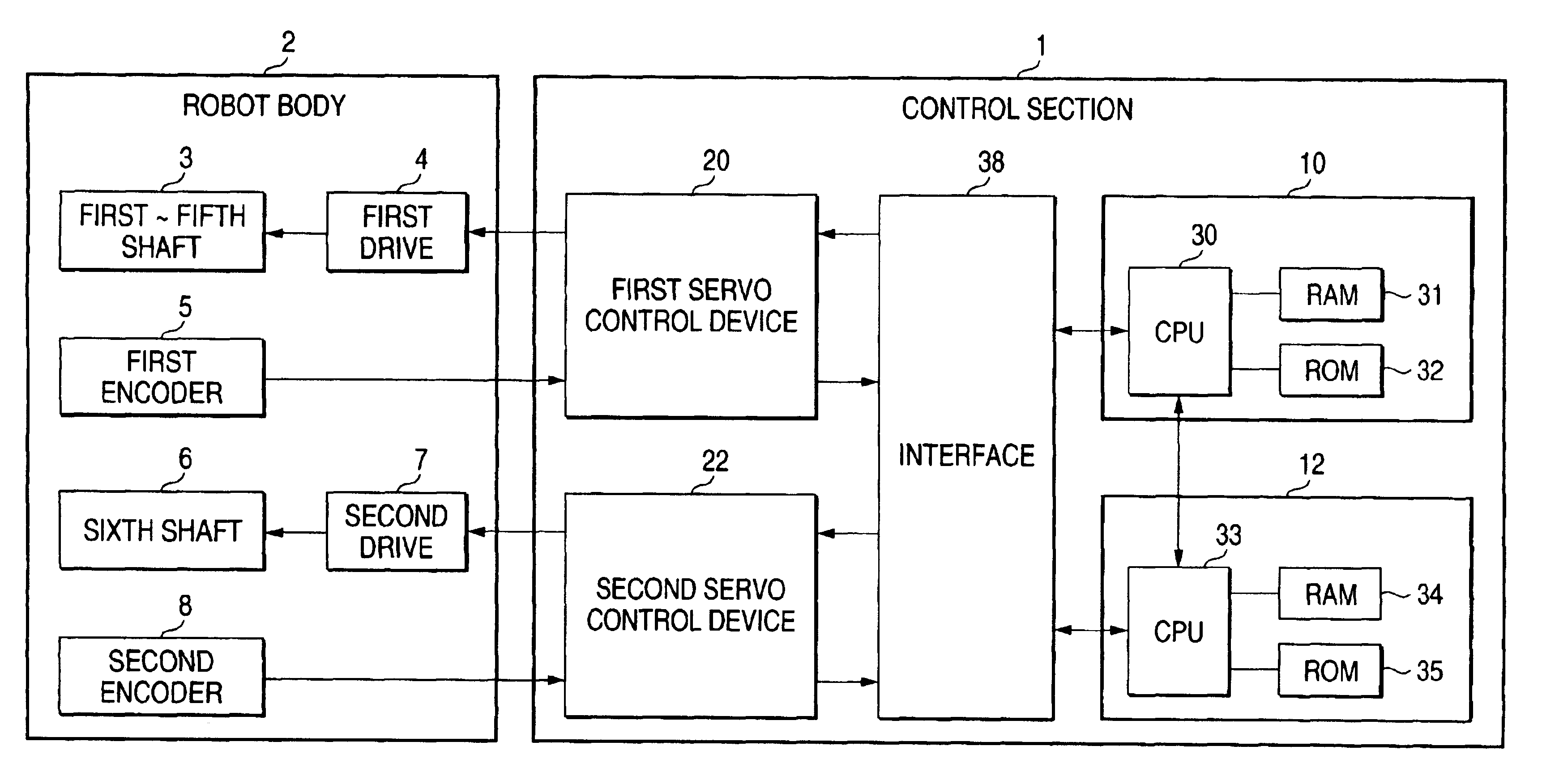
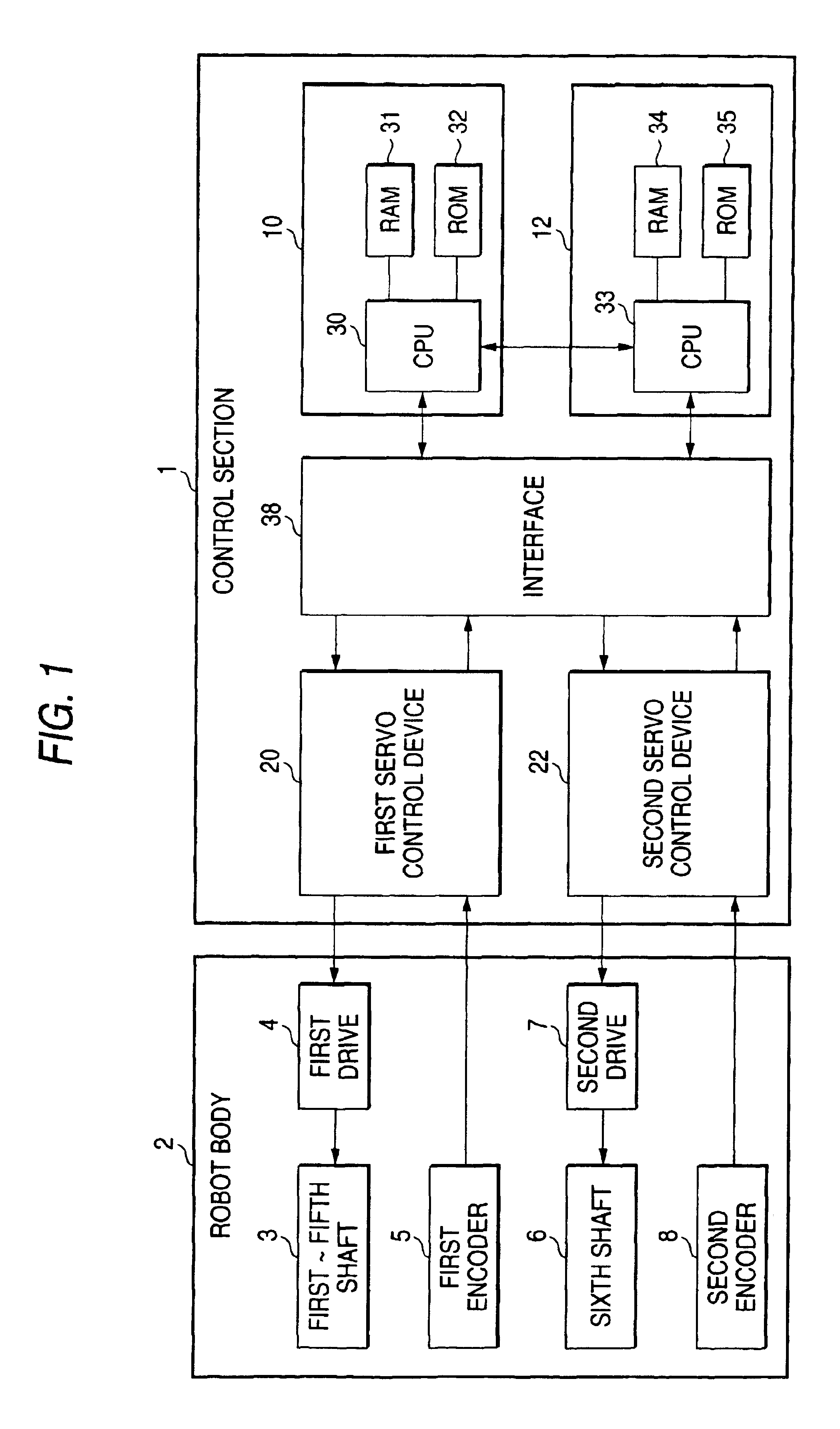
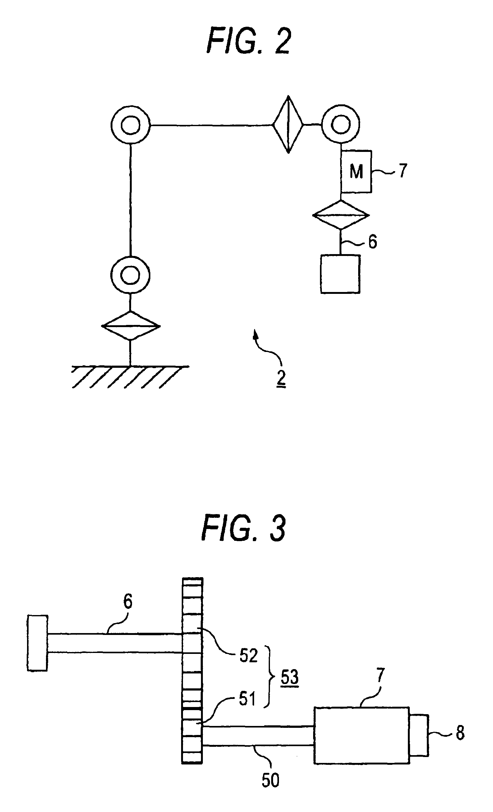
FIG. 1 is a block diagram of a robot apparatus including an infinite rotary shaft according to Embodiment 1 of the present invention, and FIG. 2 is a schematic view showing a shaft relation of a robot body. FIG. 3 is a schematic view of deceleration means of a sixth shaft.

In the drawings, a conveying apparatus comprises a robot body 2 and a control section 1. The robot body 2 includes first to fifth shafts 3 that are servo-controlled by means of a first servo control device 20 and drive and turn an arm. Further, the robot body 2 includes a sixth shaft 6 that is servo-controlled by means of a second servo control device 22 and infinitely rotates a wrist shaft mounted on a distal end portion of the fifth shaft.

Furthermore, the first to fifth shafts 3 is provided with a first encoder 5 for detecting a rotation amount thereof, and the sixth shaft 6 is provided with a second encoder 8 for detecting a rotation amount thereof. The first to fifth shafts 3 are rotationally driven by means of...

embodiment 2

A second preferred embodiment in the case of applying the invention to a conveyor is hereinafter described with reference to a schematic view of FIG. 9, a flowchart of FIG. 10 and an explanatory chart regarding a relation between an encoder value and a moving distance of FIG. 11. As shown in FIG. 9, when a drive 60 makes N rotations (e.g., 5 rotations), a conveyor 67 travels by Mmm (e.g., 18 mm), and a relation of this operation is indicated by an operation ratio R (=N / M, e.g.,=5 / 18). A difference from the arrangement in flowcharts of FIGS. 4, 5 and 6 regarding the movement processing of the reference encoder value in the infinite rotation control of the robot wrist shaft exists in using a moving distance in place of an angle in the calculation of a moving amount of the reference encoder value shown in a step S32 of FIG. 10. To calculate a moving amount of the reference encoder value, a position moving amount S in the conveyor 67, an operation ratio R of deceleration means 65 and a ...

embodiment 3

Embodiment 3 for applying the infinite rotation control apparatus according to this invention to a pick place work is hereinafter described with reference to FIGS. 12 and 13. There is provided a holding device 40 fixed to the sixth shaft 6, and this holding device 40 carry out the work holding an object 41 to be conveyed. The holding device 40 holds the object 41 to be conveyed in the form of holding it from both sides thereof. Further even if the holding device 40 rotates 180 degrees, quite the same work can be performed. That is, in the state that the sixth shaft 6 is at an angle of 0° as well as in the state that the sixth shaft 6 is at an angle of 180°, it is possible to perform quite the same holding work.

In such a work, the holding device 40 holds the object 41 to be conveyed in the state of the sixth shaft 6 being at an angle of 0 and performs a series of works, and thereafter the holding device 40 lets the object 41 off in the state of the sixth shaft 6 being at an angle of ...


PUM


Abstract

A conveying apparatus is provided with a control device for performing infinite rotation control of rotation of a strut or wrist shaft of a robot conveying an article and a drive shaft of a conveyor. The control device comprises a rotary shaft (6) rotationally driven, a drive (7) for rotating the rotary shaft, an encoder for detecting a rotation of the rotary shaft, a servo control device (22) for controlling the drive (7) based on a program command, a main control device (10) for controlling rotation, and an infinite rotation control device (12) for controlling infinite rotation. The program command is prepared and position control is carried out based on a reference encoder value. In the case of issuance of a command from a command circuit, by adding or subtracting an encoder value equivalent to a position-moving amount, the reference encoder value is changed and stored. Thus, it is possible to obtain a conveying apparatus capable of performing infinite rotation control under the state of maintaining any operation range at any deceleration ratio.

Description

TECHNICAL FIELDThe present invention relates to improvements in a conveying apparatus such as a robot, a conveyor or the like.BACKGROUND ARTHitherto, to turn a strut or a wrist shaft at a distal end portion of a robot, to drive a conveyor and the like, an infinite rotation control, in which each of rotary shafts of the robot and the conveyor performs a turn of not less than 360 degrees, has been employed.This type of conventional conveying apparatus is disclosed, for example, in Japanese Patent Laid-Open No. 79674 / 1994. In this conventional apparatus, to achieve the infinite rotation control capable of turning a wrist shaft of a robot in the order of 360 degrees and a predetermined angle positioning control by using the same hardware, the following control operation is carried out. That is, at the time of infinite rotation control, the infinite rotation is conducted by resetting a signal from an encoder mounted on a drive unit such as a motor to turn the wrist shaft each time the wr...

Claims


Application Information

Patent Timeline
IPC IPC(8): B25J13/08B25J13/00B25J9/16B25J9/10G01B21/00G01D5/245G01D5/12G06F19/00B25J9/18G05B19/418
CPCG05B19/4182Y02P90/02
Inventor HIRAKO, TOMOAKI
Owner MITSUBISHI ELECTRIC CORP
Why Eureka
Try Eureka