Programming algorithm for conical large-angle automatic fiber placement

An automatic yarn laying and large-angle technology, which is applied in the direction of calculation, special data processing applications, instruments, etc., can solve the problems of increasing and decreasing yarns, achieve the effect of simple programming method and improved laying efficiency

Active Publication Date: 2015-10-21
NANJING UNIV OF AERONAUTICS & ASTRONAUTICS
View PDF3 Cites 5 Cited by
  • Summary
  • Abstract
  • Description
  • Claims
  • Application Information

AI Technical Summary

Problems solved by technology

However, there is a problem of adding or subtracting yarns in the design of the nearly 90° fixed-angle ply track

Method used


Image

  • Programming algorithm for conical large-angle automatic fiber placement
  • Programming algorithm for conical large-angle automatic fiber placement
  • Programming algorithm for conical large-angle automatic fiber placement

Examples


Embodiment 1

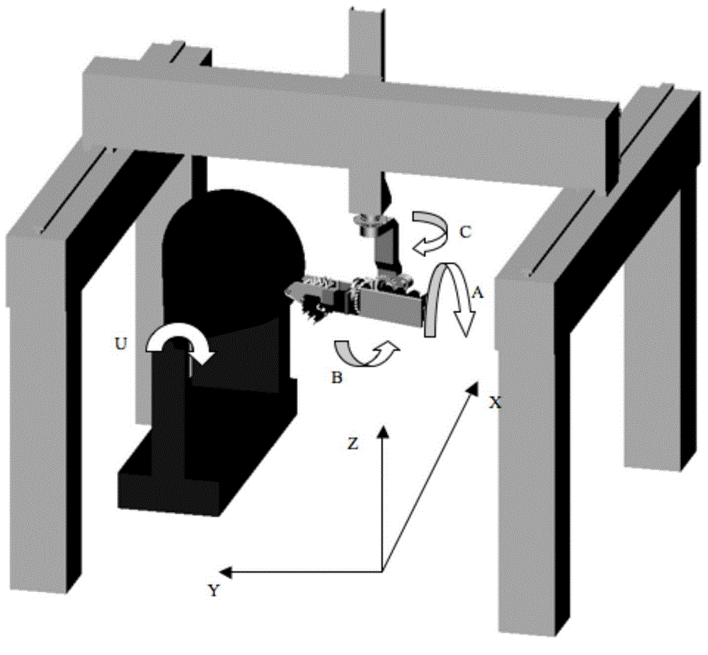
[0034] like figure 2 Shown is a gantry-type 7-axis linkage CNC laying equipment and a conical mold.

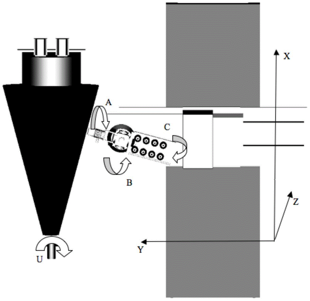
[0035] (1) Turn the B axis to the horizontal position, adjust the lifting axis Z, so that the axis of the B axis and the main shaft of the mold are in the same horizontal plane; at the same time, adjust the rotation axis C according to the semi-cone angle of the cone, so that the pressure roller is perpendicular to the horizontal generatrix of the cone; adjust the level The moving axes X and Y make the pressure roller align with the contour line of the large end surface of the cone.

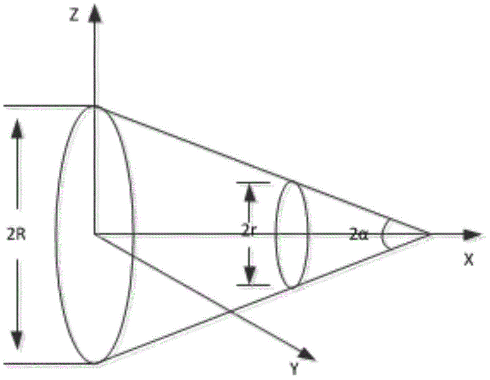
[0036] (2) According to the relationship between the conical helix angle and the pitch, calculate the helix angle of the pressure roller at the large end face of the cone shell And adjust the A-axis to this angle, where α is the semi-cone angle of the cone, and R is the radius of the large end section of the cone.

[0037] (3) Set the length x of each step of the X-axis (x

[0038] (4) Calcu...

Embodiment 2

[0041] like figure 2 Shown is composed of gantry-type 7-axis linkage CNC laying equipment and conical molds.

[0042] (1) Turn the B-axis to the horizontal position, adjust the lifting axis Z, so that the axis of the B-axis is in the same horizontal plane as the main shaft of the mold; at the same time, adjust the C-axis according to the semi-cone angle of the cone, so that the pressure roller is perpendicular to the horizontal generatrix of the cone; adjust the translation Axis X and Y, so that the pressure roller is aligned with the contour line of the small end face of the cone.

[0043] (2) According to the relationship between the conical helix angle and the pitch, calculate the helix angle of the pressure roller at the small end face of the cone shell And adjust the A-axis to this angle, where α is the semi-cone angle of the cone, and r is the radius of the small end section of the cone.

[0044] (3) Set the length x of each step of the X-axis (x>0), and calculate th...

Embodiment 3

[0048] like figure 2Shown is a gantry-type 7-axis linkage CNC laying equipment and a conical mold. First, turn the B-axis to the horizontal position, adjust the lifting axis Z, so that the axis of the B-axis is in the same horizontal plane as the main axis of the mold; at the same time, adjust the C-axis according to the semi-cone angle of the cone, so that the pressure roller is perpendicular to the horizontal generatrix of the cone; adjust the translation axis X and Y, so that the pressure roller is aligned with the contour line of the conical end surface. Secondly, according to the relationship between the cone helix angle and the pitch, calculate the helix angle of the pressure roller at the end face of the cone shell, and adjust the A axis to this angle. Finally, set the length x of each step of the X-axis, and calculate the length x tanα of each step of the Y-axis, and the rotation angle of the spindle and the amount of rotation of the A axis Output the relative va...


PUM


Abstract

The invention discloses a programming algorithm for conical large-angle automatic fiber placement. Firstly, a numerical control placement device is adjusted to enable an axis of a rotary shaft on which a pressure roll is located to be in the same horizontal plane as a main shaft of a mould, and the placement device is adjusted according to a semi-cone angle of a cone to enable the pressure roll to be located at one end of the cone and perpendicular to a horizontal bus of the cone; secondly, the placement device is adjusted according to a relation between a screw angle of the cone and a screw pitch to enable a forward direction of the pressure roll to be along a tangent direction of a spiral line at the end surface; thirdly, the step length x of a fiber placement mechanism in the axial direction of a cone housing each time is set, and the step length xtan alpha of the fiber placement mechanism in a direction perpendicular to the axis of the cone housing each time, a main rotary angle defined in the specification and a rotary angle delta beta of the pressure roll are calculated; and finally, the rotary angle delta beta is subjected to computer language programming, and the motion quantity of each shaft, corresponding to the stepping of the fiber placement mechanism in the axial direction of the cone housing each time is output, so that the programming is finished.

Description

technical field [0001] The invention belongs to the technical field of automatic laying of composite materials, and relates to a programming algorithm for automatic laying of conical large-angle wires. Background technique [0002] As a mainstream manufacturing technology for complex components of high-performance composite materials, automatic placement technology has become a standard manufacturing technology for large aerospace vehicles and is widely used in large foreign aircraft manufacturing companies. Composite conical shells are widely used in the aerospace field, such as aircraft tail cones, fuselage transition sections, etc.; in addition, composite conical shells are also increasingly used in civil fields, such as FRP retaining rings for large generators, concrete mixer trucks, etc. mixing drum etc. [0003] In the prior art, most rotary components are molded by fiber winding. However, since the pressure applied to the mold by winding molding is flexible, the fibe...

Claims


Application Information

Patent Timeline
Patent Type & Authority Applications(China)
IPC IPC(8): G06F17/50B29C70/38
Inventor 文立伟黄威肖军王显峰王跃全马丁赵聪
Owner NANJING UNIV OF AERONAUTICS & ASTRONAUTICS
Why Eureka
Try Eureka