Mechanical material guide mechanism for thread cutting on the outer surface of screws
A technology of outer surface and screw, which is applied in the field of screw processing to achieve the effect of improving flexibility
- Summary
- Abstract
- Description
- Claims
- Application Information
AI Technical Summary
Problems solved by technology
Method used
Image


Examples
Embodiment 1
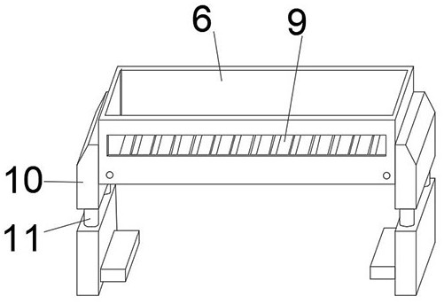
[0035] The inner middle part of the sieve box 6 is fixedly sleeved with a spliced screen frame 9, and the outer surface of the spliced screen frame 9 runs through several groups of sieve grooves 19 side by side. The setting of the screen box 6 can cooperate with the spliced screen frame 9. The sieve trough 19 is used to screen the size of the nut structure of the screw, and at the same time, the splicing replacement operation can be carried out between the sieve box 6 and the spliced screen frame 9, so that screws of different sizes are applicable.
[0036] The both sides of screen box 6 are all provided with the vibrator 10 that is used to connect fixed base 1, and the middle position of vibrator 10 is provided with buffer bar 11, utilizes the setting of vibrator 10, can make to produce shock feeling in the screen box 6, Make the screws in the sieve box 6 pass through the sieve groove 19 of the spliced screen frame 9, thereby completing the screening operation to the...
Embodiment 2
[0039] The bottom of the splicing screen frame 9 is provided with two groups of fixed clips 18, which are arranged side by side between the two groups of fixed clips 18. By using the setting of the fixed clips 18, when the spliced screen frame 9 and the sieve box 6 are installed, the splicing The bottom of the sieve frame 9 plays an auxiliary supporting role, so as to avoid falling off of the spliced sieve frame 9 .
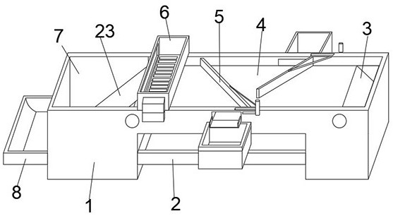
[0040] The side outer surface of the material guide rotating plate 5 is provided with an arc notch 21, and the upper part of the material guiding rotating plate 5 is movably equipped with a push-pull frame 13, utilizing the setting of the arc notch 21, the height of the material guiding rotating plate 5 can be improved. Use effect, utilize the setting of push-pull frame 13 at the same time, can drive material guide rotating plate 5 to carry out the steering adjustment operation of certain angle.
[0041] A first rotating rod 12 for connecting is arranged betw...
Embodiment 3
[0043] One end of the material guide rotating plate 5 is provided with a docking rotating shaft 22 for docking with the fixed base 1, and one end of the push-pull frame 13 is movably equipped with a rotating handle 15, and the setting of the docking rotating shaft 22 can make the material guiding rotating plate 5 rotate on the fixed base 1. The inner side of the handle is rotated and adjusted, and the rotating handle 15 is used for setting, and the rotating handle 15 can be pulled to make the rotating handle 15 cooperate with the rotating handle 15 to drive the push-pull frame 13 to move.
[0044] The inner side of one end of the fixed base 1 is provided with a discharge box 3 for circular discharge, and the inner side of the other end of the fixed base 1 is provided with a feed box 7 for adding materials. The setting of the discharge box 3 can cooperate with the first The movement of the conveyor belt 4 completes the receiving operation of some screws, and the received screws ...
PUM
 Abstract
Description
Claims
Application Information
 - R&D
- Intellectual Property
- Life Sciences
- Materials
- Tech Scout
- Unparalleled Data Quality
- Higher Quality Content
- 60% Fewer Hallucinations
Browse by: Latest US Patents, China's latest patents, Technical Efficacy Thesaurus, Application Domain, Technology Topic, Popular Technical Reports.
© 2025 PatSnap. All rights reserved.Legal|Privacy policy|Modern Slavery Act Transparency Statement|Sitemap|About US| Contact US: help@patsnap.com