Chain saw guide plate structure

A technology of chainsaw guide plate and guide plate, which is applied in the direction of chain saws, sawing equipment, working accessories, etc. It can solve the problems of the guide wheel being stuck in rotation, the outer diameter cannot be changed, and the assembly is inconvenient, so as to reduce material damage and assembly errors. efficiency and reduce waste

Pending Publication Date: 2021-08-27
胡得一
View PDF6 Cites 0 Cited by
  • Summary
  • Abstract
  • Description
  • Claims
  • Application Information

AI Technical Summary

Problems solved by technology

[0003] Assembly is often manual assembly. Among accessories, the volume of cylindrical metal parts is relatively small, and the centering collar 72 is a standard part, and its outer diameter cannot be changed. When selecting a small-sized guide wheel, only a smaller diameter can be selected. Cylindrical metal parts, resulting in very inconvenient assembly;
[0004] At the same time, the thickness of the cylindrical metal part is very close to its diameter, and assembly errors are very easy to occur during the assembly process. For example, if the cylindrical metal part is placed upright in the guide wheel, the upright position is equivalent to a state of horizontal rotation of 90 degrees , the cylindrical metal part is in contact with the inner wall of the guide wheel with a non-circular surface, causing problems such as jamming of the guide wheel rotation

Method used


Image

  • Chain saw guide plate structure
  • Chain saw guide plate structure
  • Chain saw guide plate structure

Examples


Embodiment Construction

[0029] Below in conjunction with accompanying drawing and specific embodiment the present invention is described in further detail:

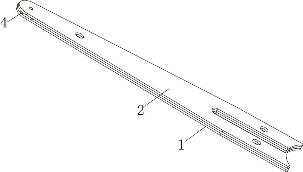
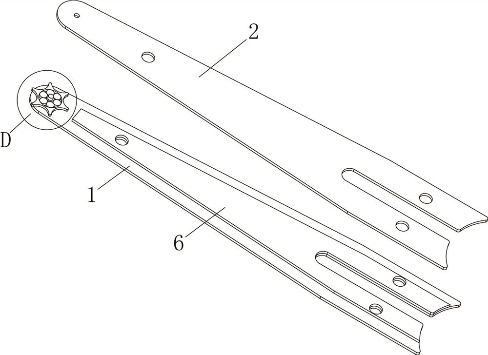
[0030] see Figure 1-Figure 5 , Chainsaw guide plate structure, including the first guide plate 1, the second guide plate 2, the connecting shaft 3, the guide wheel 4 and a number of rolling elements 5.

[0031] The first guide plate 1 and / or the second guide plate 2 includes or is provided with an intermediate guide plate 6, the first guide plate 1 and the second guide plate 2 clamp the intermediate guide plate 6 inside, and the three cooperate to form a saw chain for fitting The guide plate groove, this structure is the same as in the prior art.

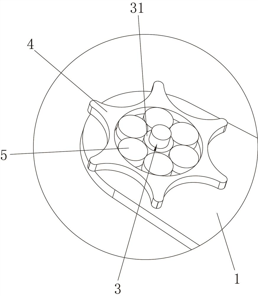
[0032] The connecting shaft 3, the rolling element 5 and the guide wheel 4 are arranged at the same end positions of the first guide plate 1 and the second guide plate 2, specifically, as figure 2 and image 3 Shown:

[0033] The guide wheel 4 includes a number of protruding teeth that match the...


PUM


Abstract

The invention discloses a chain saw guide plate structure. The chain saw guide plate structure comprises a first guide plate, a second guide plate and a guide wheel, wherein the guide wheel is arranged between the first guide plate and the second guide plate and comprises a matching hole; a connecting shaft and a rolling piece are arranged in the matching hole; the two ends of the connecting shaft are connected with the first guide plate and the second guide plate respectively, the connecting shaft comprises an integrally-formed rolling bearing part, the rolling bearing part is matched with the rolling piece and positions the guide wheel, and the guide wheel can rotate along the outer wall of the rolling piece. An existing rivet and a centering ferrule are integrated into one part, namely the connecting shaft, the step of assembling the rivet and the centering ferrule is omitted, and the assembling time can be shortened; the size of the connecting shaft can be changed, the diameter of the rolling bearing part on the integrally-formed connecting shaft can be reduced, and correspondingly, the diameter of the rolling piece can be increased, so that assembly is facilitated; and after the diameter of the rolling piece is increased, the numerical values of the diameter and the thickness of the rolling piece are changed, whether the rolling piece is horizontally arranged or vertically arranged can be obviously distinguished, and the assembly error rate is reduced.

Description

technical field [0001] The invention relates to the technical field of chain saws, in particular to the chain saw guide plate structure. Background technique [0002] The chain saw guide plate is a relatively important part of the chain saw, which provides installation and positioning space for the saw chain. The chain saw guide plate includes guide wheels, rivets 71, centering collars 72 and fillings in the guide wheels and centering collars 72 During assembly, it is necessary to place a plurality of cylindrical metal parts flatly in the guide wheel, match the circular surface with the inner wall of the guide wheel, and set the centering collar 72 on the rivet 71. Then put the two together in the enclosing circle surrounded by multiple cylindrical metal parts, such as Figure 6 and Figure 7 shown. [0003] Assembly is often manual assembly. Among accessories, the volume of cylindrical metal parts is relatively small, and the centering collar 72 is a standard part, and it...

Claims


Application Information

Patent Timeline
Patent Type & Authority Applications(China)
IPC IPC(8): B27B17/02B28D7/00
CPCB27B17/02B28D7/00
Inventor 胡得一
Owner 胡得一
Why Eureka
Try Eureka