Mechanically-connected prefabricated special-shaped pile

A mechanical connection, prefabricated technology, applied in sheet pile walls, non-rotational vibration suppression, construction, etc., can solve problems such as no quick installation

Pending Publication Date: 2021-08-27
高创建工股份有限公司
View PDF7 Cites 0 Cited by
  • Summary
  • Abstract
  • Description
  • Claims
  • Application Information

AI Technical Summary

Problems solved by technology

[0004] The purpose of the present invention is to provide a mechanically connected prefabricated special-shaped pile to solve the problem that the existing mechanically connected prefabricated special-shaped pile does not have quick installation in the background technology

Method used


Image

  • Mechanically-connected prefabricated special-shaped pile
  • Mechanically-connected prefabricated special-shaped pile
  • Mechanically-connected prefabricated special-shaped pile

Examples


Embodiment 1

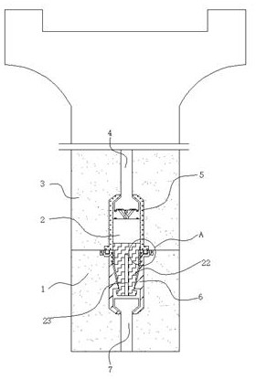
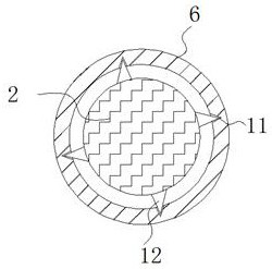
[0032] Example 1: See Figure 1-8 , a mechanically connected prefabricated special-shaped pile, including a lower prefabricated pile 1, an elastic barb tooth 12 and a locking member 22, and also includes a reinforcement mechanism 8 for a firm connection, a buffer mechanism 13 for avoiding pile breakage, and an installation for quick connection structure;

[0033] An upper prefabricated pile 3 is installed above the lower prefabricated pile 1, and an upper prefabricated installation part 5 is installed on the inner side of the upper prefabricated pile 3, and an upper prestressed steel bar 4 is installed above the upper prefabricated installation part 5, and the lower prefabricated pile 1 A lower pre-embedded installation part 6 is installed on the inner side, a lower prestressed steel bar 7 is installed under the lower embedded installation part 6, and a reinforcement mechanism 8 is installed on both sides of the top of the lower embedded installation part 6;

[0034] The inne...

Embodiment 2

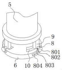
[0041] Embodiment 2: The reinforcement mechanism 8 includes a snap ring 801, a connecting column 802, and a groove 803. Grooves 803 are provided on the outer walls on both sides above the lower embedded mounting part 6, and a limiting hole 804 is provided on the side below the groove 803. , the inner side of the limit hole 804 is installed with a connecting column 802, and one end of the connecting column 802 is connected with a snap ring 801;

[0042] The other end of the connecting column 802 is connected with a mounting block 9, and the top of the embedded mounting part 6 under the mounting block 9 is provided with a mounting groove 10;

[0043] Specifically, such as figure 1 , figure 2 , Figure 4 with Figure 5 As shown, when using this structure, the installation block 9 is installed in the installation groove 10, and then the connecting column 802 is stuck in the groove 803, and then the upper prefabricated pile 3 is rotated to make the upper embedded installation par...

Embodiment 3

[0044] Embodiment 3: The buffer mechanism 13 includes a support rod 1301, a hinge 1302 and an elastic rubber block 1303. The hinge 1302 is installed on the top of the fixture 2, and both sides of the hinge 1302 are articulated with a support rod 1301. Above the hinge 1302 An elastic rubber block 1303 is installed at the bottom of the upper prestressed steel bar 4;

[0045] Limiting grooves 17 are arranged on both sides of the bottom end of the upper prestressed steel bar 4, and the top of the support rod 1301 is connected with the limiting groove 17 through the limiting block 15;

[0046] A first magnet 14 is installed on both sides of the top of the fixture 2, and a second magnet 16 is installed on the bottom of the prestressed steel bar 4 above the first magnet 14;

[0047] Specifically, such as figure 1 with Image 6 As shown, when this structure is used, the upper prefabricated pile 3 and the lower prefabricated pile 1 are subjected to impact vibration during pile sinkin...


PUM


Abstract

The invention discloses a mechanically-connected prefabricated special-shaped pile, and relates to the technical field of concrete piles. The prefabricated special-shaped pile comprises a lower prefabricated pile, elastic inverted teeth and a locking piece, and further comprises a reinforcing mechanism for firm connection, a buffering mechanism for avoiding pile breakage and an installation structure facilitating rapid connection, wherein an upper prefabricated pile is installed above the lower prefabricated pile, an upper pre-embedded installation part is installed on the inner side of the upper prefabricated pile, and an upper prestressed steel bar is installed above the upper pre-embedded installation part. The locking piece is clamped into a lower pre-embedded installation part, when the locking piece moves downward, the lower pre-embedded installation part extrudes the locking piece, an elastic telescopic block is extruded and deforms, in the descending process of the locking piece, the second slope of a clamping block is matched with the first slope of a check block, the clamping block is enabled to smoothly move downwards to the position below the check block, then the elastic telescopic block resets to enable the clamping block to rebound and be clamped below the check block to be fixed, so that quick connection of the upper pre-embedded installation part and the lower pre-embedded installation part is realized, and the problem of complicated installation is solved.

Description

technical field [0001] The invention relates to the technical field of concrete piles, in particular to a mechanically connected prefabricated special-shaped pile. Background technique [0002] After nearly 30 years of development, the product specifications of my country's prefabricated piles are becoming more and more abundant, and the matching is more reasonable. In order to improve the bending performance of the pile body and enhance the ability to resist horizontal forces, a prefabricated pile New products emerge one after another, realizing the diversification of pile foundation materials and expanding the application range of pile foundation materials. The current mechanically connected piles are cumbersome to connect, and the connection is not firm, which may easily lead to falling off and poor safety. [0003] After searching, the Chinese patent authorization announcement number CN 213358595 U, announced on June 04, 2021, discloses a mechanical connection structure...

Claims


Application Information

Patent Timeline
Patent Type & Authority Applications(China)
IPC IPC(8): E02D5/30E02D5/52F16F15/08
CPCE02D5/30E02D5/52F16F15/08
Inventor 高波吴宁娜陈勇韩天送张建新孙佳伟魏鑫鑫姬小京王高峰简征西毛钦田
Owner 高创建工股份有限公司
Why Eureka
Try Eureka