Eureka AIR delivers breakthrough ideas for toughest innovation challenges, trusted by R&D personnel around the world.

Pit type gas heater and radioactive plant system

A gas heater and pit-type technology, applied in the field of radioactive plant systems, can solve the problems of wasting time, affecting the normal operation of nuclear fuel reprocessing plants, and dangerous, and achieve the effects of convenient maintenance, ensuring safety, and avoiding condensation.

Inactive Publication Date: 2021-08-27
CHINA NUCLEAR POWER ENG CO LTD
View PDF7 Cites 0 Cited by
  • Summary
  • Abstract
  • Description
  • Claims
  • Application Information

AI Technical Summary

Problems solved by technology

Although there is a manhole on the top of the isolation room in the radioactive factory building, it is sealed with a shielding cover under normal working conditions. When the above-mentioned heating equipment needs to be maintained, the staff can enter the isolation room through the manhole for maintenance. For maintenance, the plant must first be parked, and the radioactive material liquid in the isolation room should be exported. After the isolation room is cleaned and decontaminated to reach the acceptable radiation dose for the staff, the maintenance personnel will wear gas suits and enter the isolation room for maintenance. Affecting the normal operation of nuclear fuel reprocessing plants will also waste a lot of time, and there are also certain dangers

Method used


Image

  • Pit type gas heater and radioactive plant system
  • Pit type gas heater and radioactive plant system

Examples


Embodiment 1

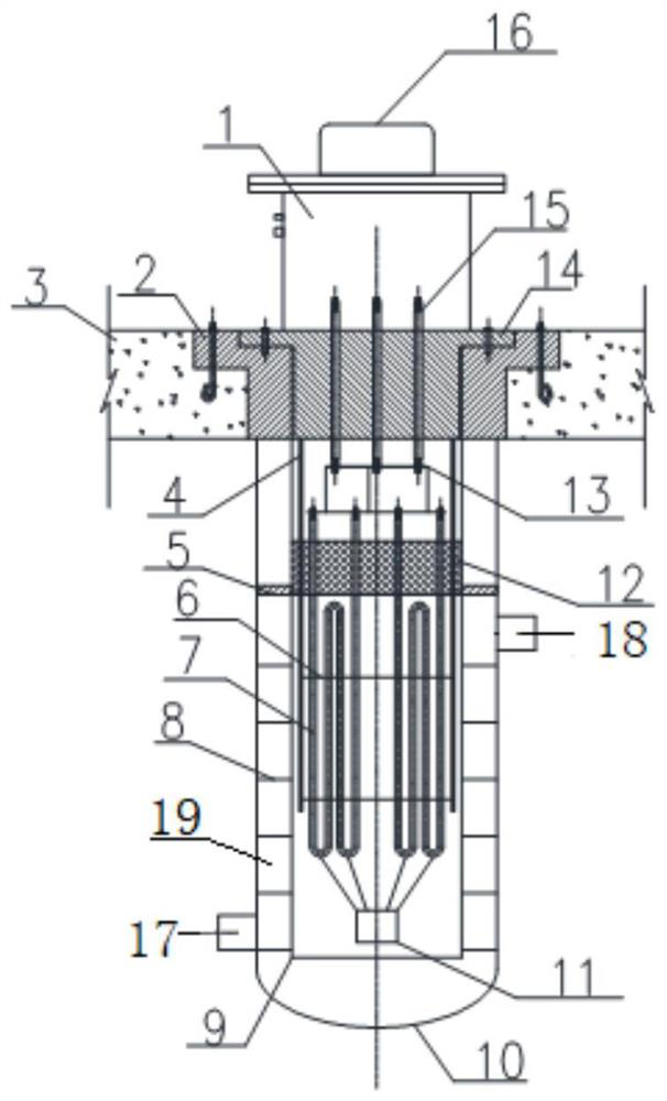
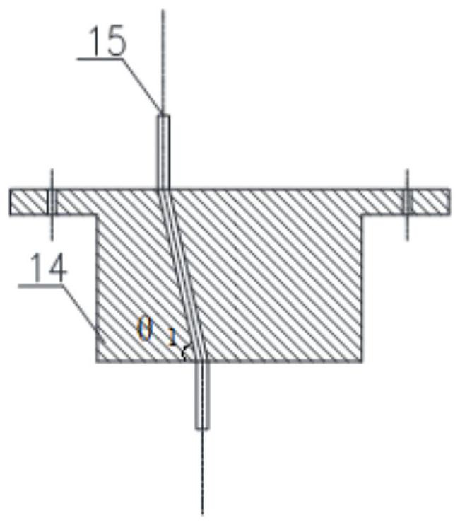
[0029] Such as figure 1 As shown, this embodiment discloses a pit-type gas heater, which includes a shell, a heating assembly, and a shielding assembly, wherein: the shielding assembly includes an inlay 2 and a penetration 14, and the inlay 2 is embedded in the roof of a radioactive place 3, the inlay 2 is provided with a first through hole, and the through part 14 is sealed in the first through hole in the form of a plug; the top of the housing is open, and the housing and the inlay 2 are connected by welding, etc., the shell The body is in the inside of the radioactive place; the heating assembly includes an electric heating tube 7 and a power lead-out rod 15, and the electric heating tube 7 is arranged inside the shell for heating the radioactive gas entering the shell from the radioactive place; the power lead-out rod 15 One end of it is electrically connected with the electric heating tube 7, and the other end passes through the through piece 14 and enters the outside of ...

Embodiment 2

[0052] This embodiment discloses a radioactive plant system, which includes an isolation room, and also includes the pit-type gas heater described in Embodiment 1, wherein the shielding assembly in the pit-type gas electric heater is embedded in the top plate of the isolation room 3, the housing is inside the isolation chamber, and the openings on the housing (i.e. the air inlet 18 and the air outlet 19) communicate with the isolation chamber. Specifically, the radioactive gas in the heat insulation chamber enters the flow channel through the air inlet 18, and is heated by the electric heating tube 7 when flowing through the flow channel 17. After heating, the radioactive gas is discharged from the gas outlet 19, and the heated The temperature of the radioactive gas can reach above 120°C.

[0053] The radioactive plant system of this embodiment, because the pit-type gas heater described in Embodiment 1 is used, can heat the radioactive gas in the isolation room, thereby avoidi...


PUM


Abstract

The invention discloses a pit type gas heater which comprises a shell body, a heating assembly and a shielding assembly, the shielding assembly comprises an insert and a penetrating piece, the insert is embedded in a top plate of a radioactive place, a first penetrating hole is formed in the insert, and the penetrating piece is arranged in the first penetrating hole in a sealed mode; a top opening of the shell body is connected with the insert, and the shell body is located in the radioactive place; the heating assembly comprises an electric heating pipe and a power source lead-out rod, and the electric heating pipe is arranged in the shell body and used for heating radioactive gas entering the shell body from the radioactive place; one end of the power source lead-out rod is electrically connected with the electric heating pipe, and the other end of the power source lead-out rod passes through the penetrating piece and enters the outside of the radioactive place. The pit type gas heater further discloses a radioactive plant system comprising the pit type gas heater. Compared with the prior art, the pit type gas heater is convenient to maintain, direct contact with radioactive gas can be avoided, maintenance-free in the isolation room of the radioactive plant is realized, and the safety of maintenance personnel is ensured.

Description

technical field [0001] The invention belongs to the field of nuclear technology, and in particular relates to a pit-type gas heater and a radioactive plant system including the pit-type gas heater. Background technique [0002] During the production process of radioactive factories, a large amount of radioactive gases will be produced, and these radioactive gases need to be purified before they can be discharged. During the purification process, in order to avoid condensation of water vapor entrained in the radioactive gas in the filter, it is necessary to heat the radioactive gas to above 120°C before it enters the filter. [0003] At present, tube-and-tube heat exchangers are usually used for steam heating or ordinary pipe-type electric heating equipment. Considering the containment of radioactive substances, the above-mentioned equipment needs to be placed in an isolation room, and the isolation room must be surrounded by thick concrete for protection. Although there is ...

Claims


Application Information

Patent Timeline
Patent Type & Authority Applications(China)
IPC IPC(8): F24H3/00F24H9/02F24H9/00F24H9/18G21F9/02
CPCF24H3/002F24H9/02F24H9/0063F24H9/0052F24H9/1863G21F9/02F24H2250/02
Inventor 翁展崔皎刘江海徐琰武毓勇马敬刘昱祺贾惠敏张惟睿
Owner CHINA NUCLEAR POWER ENG CO LTD
Why Eureka
Eureka Blog
Learn More