
Calculation method and application of limited wind speed for key smoke exhaust at the side of tunnel

A calculation method and wind speed technology, which are applied in the field of tunnel fire smoke control, can solve the problems such as the calculation method of limited wind speed of tunnel fire in the key smoke exhaust mode on the side, etc., and achieve a simple, scientific and effective method. Effect

Active Publication Date: 2022-05-20
WUHAN UNIV OF SCI & TECH
View PDF7 Cites 0 Cited by
  • Summary
  • Abstract
  • Description
  • Claims
  • Application Information

AI Technical Summary

Problems solved by technology

The current research mainly explores the calculation method of the critical wind speed. The critical wind speed is the longitudinal wind speed that just makes the smoke counterflow length zero, which can ensure that there is no smoke upstream of the fire source. However, the critical wind speed is used to control the spread of smoke. On the one hand, due to the critical wind speed Theoretically, it is greater than the limited wind speed, so the smoke cannot be exhausted to the nearest upstream smoke outlet; The heat release rate of the fire source is related to the distance between the non-dimensional smoke outlet and the fire source. Therefore, the longitudinal wind speed predicted by the critical wind speed model controls the counterflow of smoke, which is still affected by the change of smoke discharge.
[0004] At present, most of the existing limited wind speed calculation methods are aimed at the situation where the smoke exhaust outlet is located at the top of the tunnel. The limited wind speed is determined according to the ratio of the length of the counterflow of the smoke to the tunnel height. The mouth is located on the side wall of the tunnel. Compared with the smoke exhaust at the top, the stress state and motion state of the smoke have changed at this time. There is no calculation method for the limited wind speed of the tunnel fire in the side key smoke exhaust mode at home and abroad.

Method used


Image

  • Calculation method and application of limited wind speed for key smoke exhaust at the side of tunnel
  • Calculation method and application of limited wind speed for key smoke exhaust at the side of tunnel
  • Calculation method and application of limited wind speed for key smoke exhaust at the side of tunnel

Examples


Embodiment Construction

[0040] The principles and features of the present invention will be described below in conjunction with the accompanying drawings and specific embodiments. The examples given are only used to explain the present invention and are not intended to limit the scope of the present invention.

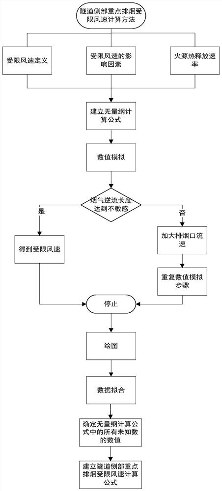
[0041] like Figure 1 to Figure 5 As shown, the present invention provides a calculation method for the restricted wind speed of a key smoke exhaust fire at the side of a tunnel, including the following specific steps:

[0042] S1: Determine the restricted wind speed u in the tunnel fire scene c The definition of : the minimum longitudinal induced wind speed corresponding to the flue gas reverse flow length is not sensitive to the fluctuating smoke outlet velocity is called the limited wind speed u c , the smoke backflow length refers to the distance between the fire source and the smoke outlet in the direction of tunnel travel.

[0043] S2: Determine the restricted wind speed u in the tunn...


PUM


Abstract

The invention relates to a calculation method and application of a restricted wind speed for key smoke exhaust at the side of a tunnel, comprising the following specific steps: determining the restricted wind speed u c The definition of , determine the influencing factors, and establish the limited wind speed u c Relationship with influencing factors; determine the basic dimension and establish the limited wind speed u c Dimensional relationship with the influencing factors; determine the basic physical quantity, obtain the dimensionless items of the influencing factors according to the π theorem, and derive the limited wind speed u c The dimensionless calculation formula; through numerical simulation, the value of the smoke counterflow length L of the fire under different working conditions is obtained, and the restricted wind speed is obtained through the smoke counterflow length, and the simulation results are drawn into a scatter diagram to clarify the impact of the influencing factors on the restricted wind speed u c influence; data fitting is performed on the above results to obtain the values ​​of the unknown coefficients in the dimensionless relational formula, and then establish the dimensionless limited wind speed u c calculation formula. The beneficial effect is that the method is simple, applicable to different tunnels, has a great impact on the efficient use of the tunnel smoke exhaust capacity, and provides guidance for fire smoke control and fire rescue in key side smoke exhaust tunnels.

Description

technical field [0001] The invention relates to the technical field of tunnel fire smoke control, in particular to a calculation method and application of a limited wind speed for key smoke exhaust at the side of a tunnel. Background technique [0002] Fire is one of the biggest risks to tunnel operations. Due to the narrow and closed characteristics of the tunnel, the tunnel has a unique spatial structure and fire characteristics compared with ordinary ground buildings. Once a fire breaks out in the tunnel, the smoke cannot be discharged in time, which can easily cause suffocation or poisoning, and secondary damage will occur if the vehicles in the tunnel leave too late, resulting in a major catastrophic accident involving mass death and mass injury. Controlling the limited wind speed is conducive to the efficient use of the smoke exhaust capacity of the tunnel, and the control of the smoke within a certain range to ensure personnel evacuation and rescue. [0003] Restric...

Claims


Application Information

Patent Timeline
Patent Type & Authority Patents(China)
IPC IPC(8): G06F30/20G06F111/10
CPCG06F30/20G06F2111/10Y02T90/00
Inventor 姜学鹏刘婵
Owner WUHAN UNIV OF SCI & TECH
Learn More